Frequently Asked Questions
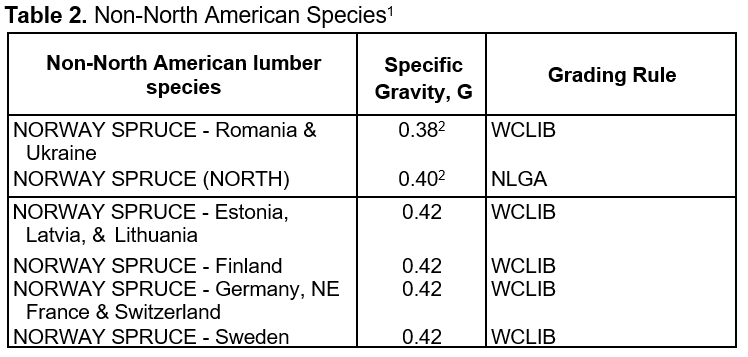
See Tables 1 and 2 for visually graded lumber species and lumber species combinations and assigned specific gravity per the National Design Specification (NDS) for Wood Construction. Assigned specific gravity in the NDS is an average property based on weight and volume when oven-dry. Bold entries are commonly available lumber species combinations used in International Residential Code and International Building Code span tables for joists and rafters.
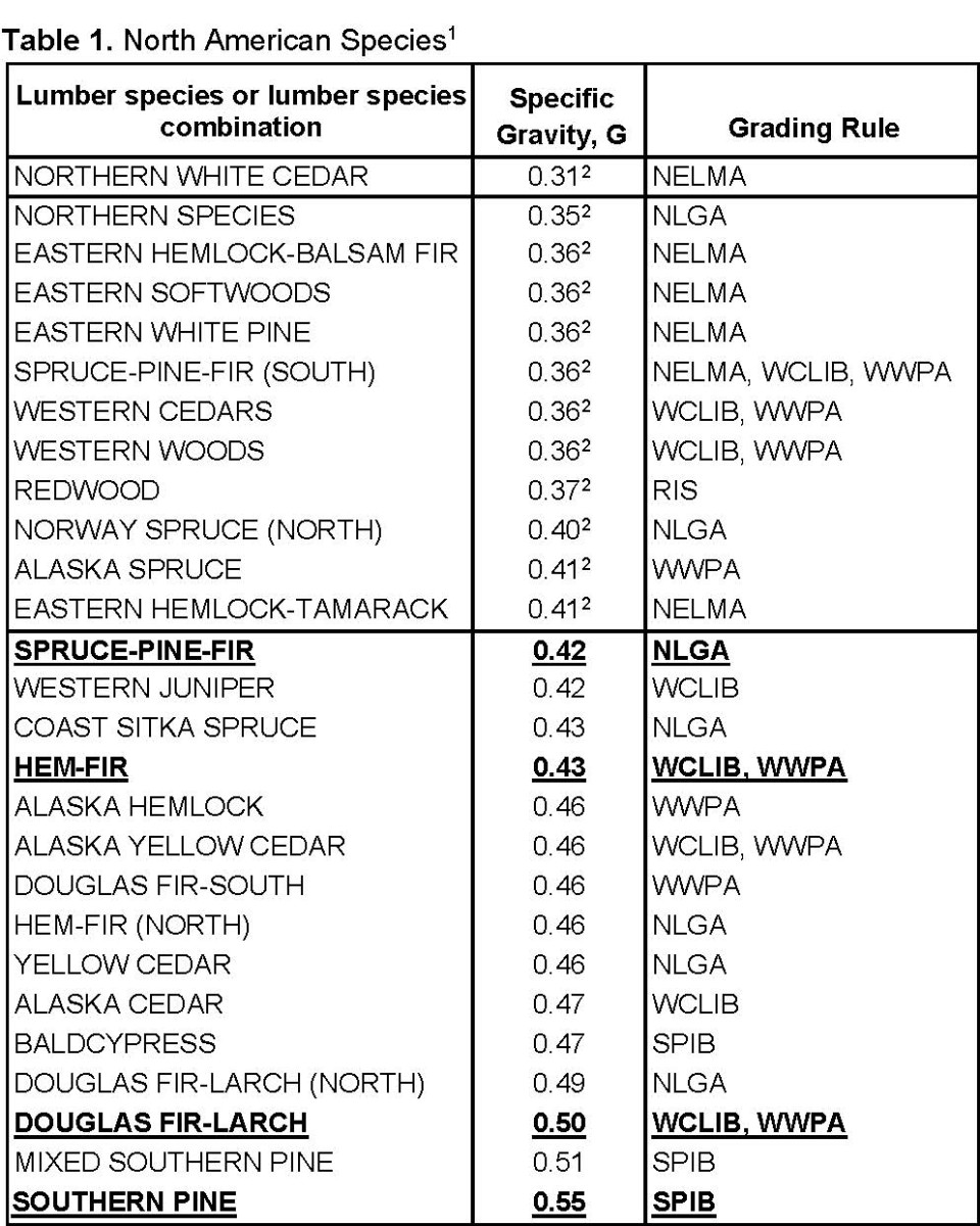
- For a complete listing of lumber species, lumber species combinations and assigned specific gravity, see NDS Supplement Chapter 4 and its Addendum/Errata.
- Lumber with specific gravity less than 0.42 may be associated with special prescriptive fastening requirements in accordance with the International Residential Code (IRC) and International Building Code (IBC). Bold entries are commonly available lumber species combinations used in IRC and IBC span tables for joists and rafters.
- For a complete listing of lumber species, lumber species combinations and assigned specific gravity, see NDS Supplement Chapter 4 and its Addendum/Errata.
- Lumber with specific gravity less than 0.42 may be associated with special prescriptive fastening requirements in accordance with the International Residential Code (IRC) and International Building Code (IBC).
A list of lumber grading rules writing organizations certified by the American Lumber Standards Committee (ALSC) is provided below.
- NELMA. Standard Grading Rules for Northeastern Lumber; published by the Northeast Lumber Manufacturers Association (NELMA), 272 Tuttle Road, P.O. Box 87A, Cumberland Center, ME 04021; 207.829.6901; 207.829.4293 (fax); e-mail [email protected]
- RIS. Standard Specifications for Grades of California Redwood Lumber; published by the Redwood Inspection Service (RIS), 1500 SW First Avenue, Portland Oregon 97204-2122; 503.224.3930; 503.224.3934 (fax); e-mail [email protected]
- SPIB. Standard Grading Rules for Southern Pine; published by the Southern Pine Inspection Bureau (SPIB), 4555 Spanish Trail, Pensacola, FL 32504; 850.434.2611; 850.434.1290 (fax); e-mail [email protected]
- PLIB/WCLIB. Standard Grading Rules for West Coast Lumber; published by the Pacific Lumber Inspection Bureau (PLIB/WCLIB); 1010 South 336th Street, Suite 210, Federal Way, WA 98003; 253.835.3344; 253.835.3371 (fax); e-mail [email protected]
- WWPA. Western Lumber Grading Rules; published by Western Wood Products Association (WWPA); 1500 SW First Avenue, Portland Oregon 97204-2122; 503.224.3930; 503.224.3934 (fax); e-mail [email protected]
- NLGA. Standard Grading Rules for Canadian Lumber; published by the National Lumber Grades Authority (NLGA); Suite 303 – 409 Granville St., Vancouver, BC V6C 1T2; 604.673.9100; 604.673.9141; e-mail [email protected]
For the most up to date information see: https://alsc.org/lumber-grade-rules-organizations/
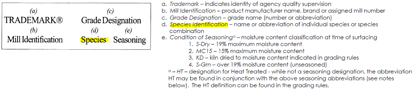
With few exceptions, lumber species or lumber species combination (usually in abbreviated form) is a standard component of lumber grade stamps per the American Lumber Softwood Lumber Standard – PS20.
These grade mark components are illustrated below for Visually Graded Lumber.
An example grade stamp for S-P-F (or Spruce-Pine-Fir) lumber species combination is shown below:
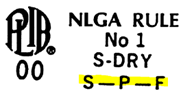
If lumber species or lumber species combinations questions arise based on grade stamp notations, the inspection agency for this example (i.e., Pacific Lumber Inspection Bureau) should be contacted:
See (http://alsc.org/uploaded/LumberProgram_facsimile%20September%202021.pdf) for more information on grade stamps including inspection agency contact information.
Where can I obtain information on designing post frame structures (sometimes referred to as pole buildings or pole barns)?
1. Design values for poles (smaller at the top and buried) and piles (smaller at the bottom and driven) are in the 2005 NDS Chapter 6. Design values for poles and piles were moved to the NDS Supplement: Design Values for Wood Construction in the 2012 Edition.
2. Post-Frame Design Manual (Second Edition) to be published by the Technical & Research Committee of the National Frame Builders Association (NFBA).
NFBA
4840 Bob Billings Parkway
Lawrence, KS 66049-3862
Phone: (800) 557-6957
Local: (785) 843-2444
Fax: (785) 843-7555
E-mail: [email protected]
Website: NFBA (National Frame Building Association)
3. ASAE Post Frame Building Manual
ISBN: 0-929355-29-6
Phone: 800-695-2723
Fax: 269-429-3852
4. The Midwest Plan Service publishes a Structures and Environment Handbookwhich address gussets in section 406.5 under Wood Truss Design. The most recent edition is a 1987 Revised 11th Edition. For ordering information, visit
https://www-mwps.sws.iastate.edu/catalog/construction-farm/structures-and-environment-handbook
Midwest Plan Service
122 Davidson Hall
Iowa State University
Ames, IA 50011-3080
Toll Free: (800) 562-3618
E-mail: [email protected]
Design for Code Acceptance (DCA) #5 provides guidance to post-frame building designers for meeting the requirements of the 2000 International Building Code and to confirm that a properly designed post-frame building is in fact code compliant.
See also General FAQ: “Where can I find information on Timber Poles and Piles?”
See also General FAQ: “What is timber frame construction and where do I find more information about it?”
The Southern Forest Products Association (SFPA) publishes the Permanent Wood Foundations Design and Construction Guide. Download the document here.
AWC’s PWF Design Fabrication Installation (DFI) Manual and Technical Report #7, Permanent Wood Foundation System Basic Requirements (TR7) have both been discontinued and are out of print. ANSI / AWC PWF – Permanent Wood Foundation Design Specification replaces TR7 and has been adopted in the 2009/2012 International Residential Code and 2009/2012 International Building Code. This document primarily addresses structural design requirements. See the SFPA Permanent Wood Foundations Design and Construction Guide for construction details and tabulated data.
- Designing Retaining Walls, Bulkheads and Seawalls of Treated Timber. Author: American Wood Preservers Institute, 1966
- Earth Retaining Structures. Author: W.D. Keeney, AWPI
- Improved Standard Designs Pressure-Treated Timber Crib Walls. AWPI, 1969.
- Available upon e-mail request: [email protected].
Guidance for this issue can be found in the commentary to the Permanent Wood Foundation Design Specification. The PWF commentary states in C5.4.5:
- Since nominal unit shear capacities for shear walls and diaphragms published in the Special Design Provisions for Wind and Seismic (SDPWS) Specification are based on short-term load duration, it is necessary to multiply nominal unit shear capacities for seismic by 0.281. The 0.281 multiplier results from the combination of the 2.0 allowable stress design (ASD) reduction factor and a 0.9/1.6 factor for adjusting from the ten-minute load duration basis for wind and seismic design in the SDPWS to a permanent load duration basis for PWF applications.
Anchor bolt connections designed per SDPWS 4.3.6.4.3 are designed for the shear load in the sill plate. If the shear capacity of a double-sided shear wall is twice that of a single-sided shear wall, the anchor bolt spacing derived based on the anchor bolt shear capacity for a double-sided shear wall would be half the spacing of a single-sided shear wall. Staggering the anchor bolts 1/2″ from the plate edge for a double-sided shear wall provides uplift resistance on each edge of the sill plate equivalent to a single row of anchor bolts located 1/2″ from the plate edge on a single-sided shear wall.
The National Design Specification® (NDS®) Supplement tables list design values for 2x and larger decking.
The American Lumber Standards Committee (ALSC) provides a Policy for Evaluation of Recommended Spans for Span Rated Decking Products. Here’s more information on their website:
https://alsc.org/lumber-recommended-spans-for-decking/
You will need to contact the specific grading agencies to obtain their span ratings for various species. A list of those agencies is on the ALSC website as well.
Lateral design values for lumber diaphragms and shear walls are available in Special Design Provisions for Wind and Seismic.
See also General FAQ, “Where can I get span tables and span table information for lumber? Where can I get decking span tables?” for span information on decking.
Also see Tongue and Groove Roof Decking – WCD #2.
Also see Plank-And-Beam Framing for Residential Buildings – WCD #4.
AWC’s Special Design Provisions for Wind and Seismic, Table 4.2D contains shear capacities for lumber sheathing attached straight and diagonally. Table 4.3D contains shear wall capacities for straight and diagonal lumber sheathing as well.
AWC also publishes Plank and Beam Framing for Residential Buildings (WCD-4) (T14). It shows how this floor and roof framing system, traditionally used in heavy timber structures, can be adapted to home building.
The International Building Code contains design capacities for diagonally sheathed lumber diaphragms in section 2306.3 Wood Diaphragms. Visit http://www.iccsafe.org for ordering information.
Analysis Methods for Horizontal Wood Diaphragms by Jephcott and Dewdney from proceedings of a Workshop on Design of Horizontal Wood Diaphragms (ATC-7-1) conducted by Applied Technology Council on November 19-20, 1980 (25 pages). Visit their website at http://www.atcouncil.org/ to order.
Table 3.17D in the Wood Frame Construction Manual provides maximum shear wall segment aspect ratios for various wood and gypsum assemblies. Also see Special Design Provisions for Wind and Seismic Table 4.3.4. Typically, 3.5:1 is the maximum aspect ratio for design of blocked wood structural panel shear walls. For an 8′ tall shear wall, that would mean 27-1/2″ of full-height sheathing.
The segmented shear wall method considers each full-height segment individually, and has hold-downs at the ends of each full-height segment. The perforated shear wall method only requires hold downs at the very ends of the shear wall length. Both methods are covered in various AWC standards including Special Design Provisions for Wind and Seismic and the Wood Frame Construction Manual.
![]() Read the Perforated Shear Wall Design PDF for more information.
Read the Perforated Shear Wall Design PDF for more information.
Values of apparent shear stiffness, Ga, are tabulated in seismic columns of the SDPWS to facilitate calculation of seismic story drift in accordance with ASCE 7 Minimum Design Loads for Buildings and Other Structures. Values of Ga are equally applicable for calculation of the shear deformation component of total deflection due to wind loads up to the ASD wind unit shear value calculated as vw/2.0. This level of unit shear for wind is identical to 1.4 times the ASD seismic unit shear capacity for which apparent shear stiffness values were originally developed (see SDPWS Commentary C4.2.2).
AWC Wood Frame Construction Manual (WFCM) 2015 Edition is presently referenced in model building codes such as the IBC (International Building Code) and IRC (International Residential Code). The WFCM is an ANSI-approved document that provides engineered and prescriptive requirements for wood frame construction based on dead, live, snow, seismic, and wind loads from ASCE 7-10 Minimum Design Loads for Buildings and Other Structures.
AWC Special Design Provisions for Wind and Seismic (SDPWS) 2015 Edition is presently referenced in model building codes such as the IBC. The SDPWS is an ANSI-approved document that covers materials, design, and construction of wood members, fasteners, and assemblies to resist wind and seismic forces.
Wood has a high strength-to-weight ratio. Since wood is lighter than steel or concrete, there is less mass to move—a critical factor during an earthquake. Wood members connected with steel fasteners create a very ductile (flexible) assembly which is less prone to brittle failures often seen with unreinforced masonry or concrete structures.
Multiple, repetitive wood members (studs, joists, and rafters at 16”-24” on-center) provide redundancy in wood assemblies making them less prone to catastrophic collapse. Wood’s renewability, low life-cycle environmental impacts, and ability to sequester carbon provides the optimal combination of green building and stability for earthquake-prone areas.
Tests have proven the viability of wood frame structures under seismic loads.
For the perforated shear wall method, the internal vertical members are not designed to resist tension due to overturning; but for compression due to overturning the design force would be the same as would result from using a segmented shear wall method. See Special Design Provisions for Wind and Seismic and the Wood Frame Construction Manual.
![]() Read the Perforated Shear Wall Design PDF for more information.
Read the Perforated Shear Wall Design PDF for more information.
Guidance for this issue can be found in the commentary to the Permanent Wood Foundation Design Specification. The PWF commentary states in C5.4.5:
- Since nominal unit shear capacities for shear walls and diaphragms published in the Special Design Provisions for Wind and Seismic (SDPWS) Specification are based on short-term load duration, it is necessary to multiply nominal unit shear capacities for seismic by 0.281. The 0.281 multiplier results from the combination of the 2.0 allowable stress design (ASD) reduction factor and a 0.9/1.6 factor for adjusting from the ten-minute load duration basis for wind and seismic design in the SDPWS to a permanent load duration basis for PWF applications.
A splice is a means of connecting discontinuous top plate members to transfer the design tension force. For the design assumptions in the WFCM, all top plate joints must be spliced in order to maintain diaphragm chord tension capacity. See WFCM Table 3.21 for top plate splice requirements.
The following design standards for wood construction in high wind areas are presently referenced in model building codes such as the IBC (International Building Code) and IRC (International Residential Code):
1. AWC Wood Frame Construction Manual (WFCM) 2015 Edition
2. ICC Standard for Residential Construction in High Wind Regions (ICC-600)
The WFCM is an ANSI approved document that provides engineered and prescriptive requirements for wood frame construction based on dead, live, snow, seismic and wind loads derived from the ASCE 7-10 Minimum Design Loads for Buildings and Other Structures.
ICC-600 presents prescriptive methods to provide wind resistant designs and construction details for residential buildings. The standard is an update to SSTD 10-99 and includes new provisions such as prescriptive designs for wind speeds up to 150 mph with three-second gusts and exterior wall coverings for high wind.
AWC’s Wood Frame Construction Manual (WFCM) for One- and Two-Family Dwellings prescriptively limits cantilevers based on the following conditions, where L is the length of the simple span, center to center of bearing and d is the depth of the joist:
Loadbearing wall, shear wall or non-shear wall <= d
Non-loadbearing, shear wall or non-shear wall <= L/4
Non-loadbearing shear wall <=4d
AWC’s Special Design Provisions for Wind and Seismic, Table 4.2D contains shear capacities for lumber sheathing attached straight and diagonally. Table 4.3D contains shear wall capacities for straight and diagonal lumber sheathing as well.
AWC also publishes Plank and Beam Framing for Residential Buildings (WCD-4) (T14). It shows how this floor and roof framing system, traditionally used in heavy timber structures, can be adapted to home building.
The International Building Code contains design capacities for diagonally sheathed lumber diaphragms in section 2306.3 Wood Diaphragms. Visit http://www.iccsafe.org for ordering information.
Analysis Methods for Horizontal Wood Diaphragms by Jephcott and Dewdney from proceedings of a Workshop on Design of Horizontal Wood Diaphragms (ATC-7-1) conducted by Applied Technology Council on November 19-20, 1980 (25 pages). Visit their website at http://www.atcouncil.org/ to order.
Table 3.17D in the Wood Frame Construction Manual provides maximum shear wall segment aspect ratios for various wood and gypsum assemblies. Also see Special Design Provisions for Wind and Seismic Table 4.3.4. Typically, 3.5:1 is the maximum aspect ratio for design of blocked wood structural panel shear walls. For an 8′ tall shear wall, that would mean 27-1/2″ of full-height sheathing.
AWC Wood Frame Construction Manual (WFCM) 2015 Edition is presently referenced in model building codes such as the IBC (International Building Code) and IRC (International Residential Code). The WFCM is an ANSI-approved document that provides engineered and prescriptive requirements for wood frame construction based on dead, live, snow, seismic, and wind loads from ASCE 7-10 Minimum Design Loads for Buildings and Other Structures.
AWC Special Design Provisions for Wind and Seismic (SDPWS) 2015 Edition is presently referenced in model building codes such as the IBC. The SDPWS is an ANSI-approved document that covers materials, design, and construction of wood members, fasteners, and assemblies to resist wind and seismic forces.
Wood has a high strength-to-weight ratio. Since wood is lighter than steel or concrete, there is less mass to move—a critical factor during an earthquake. Wood members connected with steel fasteners create a very ductile (flexible) assembly which is less prone to brittle failures often seen with unreinforced masonry or concrete structures.
Multiple, repetitive wood members (studs, joists, and rafters at 16”-24” on-center) provide redundancy in wood assemblies making them less prone to catastrophic collapse. Wood’s renewability, low life-cycle environmental impacts, and ability to sequester carbon provides the optimal combination of green building and stability for earthquake-prone areas.
Tests have proven the viability of wood frame structures under seismic loads.
AWC’s Wood Construction Data #1 Details for Conventional Wood Frame Construction, which provides proper methods of construction in wood frame buildings, with information on features which contribute to the satisfactory performance of wood structures.
AWC publishes the Wood Frame Construction Manual for One- and Two-Family Dwellings to provide solutions based on engineering analysis, in accordance with recognized national codes and standards. Like conventional construction, the engineered solutions are provided in a prescriptive format.
The WFCM does not require special consideration of floor plan offsets up to 4′. If the floor plan offset exceeds 4′ deep, the provisions of 1.1.3.3a would apply. The building would be designed as:
1) separate structures attached at the wall line at the offset(s); or,
2) a rectangular building with perimeter dimensions that inscribe the entire structure including the offsets.
The appropriate design method would be decided by the complexity of the building shape and the load path required to transfer the forces.
The WFCM uses the envelope procedure, which is a simplified method where GCpf values are developed to provide maximum structural actions from boundary-level wind tunnel tests of low-rise buildings meeting certain limitations. The directional procedure uses GCp values that are based on general aerodynamic theory and is more generally applicable to all buildings.
Exposure B as defined in the WFCM and ASCE7-10 is as follows: “Urban and suburban areas, wooded areas, or other terrain with numerous closely spaced obstructions having the size of singe family dwellings or larger.”
Exposure C as defined in the WFCM and ASCE7-10 is as follows: “Open terrain with scattered obstructions including surface undulations or other irregularities having height generally less than 30 feet extending more than 1500 feet from the building site in any quadrant. Exposure C extends into adjacent Exposure B type terrain in the downwind direction for the distance of 1500 feet or 10 times the height of the building or structure, whichever is greater. This category includes open country and grasslands, and open water exposure for less than 1 mile.”
Exposure D as defined in the WFCM is as follows: “Flat unobstructed areas exposed to wind flowing over open water for a distance of a least 1 mile. This exposure shall apply only to those buildings and other structures exposed to the wind coming from over the water. Exposure D extends inland from the shoreline a distance of 1500 feet or 10 times the height of the building or structure, whichever is greater.” The ASCE7-10 definition is similar.
Exposure D is outside the scope of Chapter 3 of the WFCM. It would require either design using WFCM Chapter 2 or ASCE 7. Conversion factors for Exposure D are available in WFCM Table 2.1.3.1 and their applicability is noted in Chapter 2 Table footnotes.
Yes. For each wind direction, there can be a different exposure.
In the WFCM, Mean Roof Height is defined as “the distance from the average grade to the average roof elevation.” See WFCM Figure 1.2.
The WFCM is limited to a Mean Roof Height (MRH) of 33′ or less, but the envelope method in ASCE 7-10 that is used in the WFCM has a limit of 60′.
No. Portal frames are outside the scope of the WFCM.
There are currently no WFCM Excel, Mathcad, or other pre-programmed sheets for general use. There is an online span and connection calculator that can be accessed through the AWC website, www.awc.org. Also, WoodWorks Software includes a shear wall module that generates wind pressure and resulting diaphragm loads per ASCE 7-10.
The WFCM designs with exterior shear walls. If the building is broken into individual separate structures, there would be interior shear walls that extend to the roof diaphragm unless an alternative design is provided.
Yes. WFCM Section 3.2.6.1 requires ridge straps, but provides an exception for collar ties: “Ridge straps are not required when collar ties (collar beams) of nominal 1×6 or 2×4 lumber are located in the upper third of the attic space and attached to rafters in accordance with Table A-3.6.”
See the following article for more information:
http://www.jlconline.com/roofing/conventional-roof-framing-a-codes-eye-view_o.aspx
All roof and wall sheathing designs are based on 8d common or 10d box nails, regardless of sheathing type or thickness. Table 3.1 in the WFCM provides a complete nailing schedule.
For unblocked diaphragms, the blocking requirements for floor and roof diaphragm bracing to transfer wind loads from exterior walls into the floor/roof diaphragm are based on the number of bay spacings required to get the load into the floor and roof sheathing. See WFCM 3.3.5 and 3.5.5.
See WFCM section 3.5.1.3 for depth to thickness ratios requiring blocking. Shear transfer through rafter/ceiling joist to top plate connections is assumed to happen without blocking if depth-to-thickness ratios are in accordance with WFCM 3.5.1.3. This is for diaphragm capacities in accordance with WFCM chapter 3 requirements
Connectors should be detailed to align the uplift load on the same side of the stud avoiding cross grain bending in the top plate. See WFCM Figure 3.2k for an example.
From the WFCM Commentary: “Uplift for design of rafters, roof cladding, and roof sheathing attachment is calculated using Components and Cladding (C&C) loads. Uplift connections for roof assemblies are calculated using enveloped Main Wind Force-Resisting System (MWFRS) loads. The rationale for using MWFRS loads for computing the uplift of roof assemblies recognizes that the spatial and temporal pressure fluctuations that cause the higher coefficients for components and cladding are effectively averaged by wind effects on different roof surfaces consistent with the definitions of C&C and MWFRS loads in ASCE 7. Also note that C&C loads are used to calculate wall bending loads whereas MWFRS loads are used to calculate combined bending and axial loads. Within the scope of the WFCM, C&C bending loads control.” See the following paper for more details:
Considerations in Wind Design of Wood Structures ![]()
Yes. See WFCM 3.2.6.1 for ridge connection requirements.
Yes. WFCM Section 3.4.4.2.3 allows a single hold-down to be used to resist overturning forces in both directions where full height shear wall segments meet at a corner, provided the corner framing in the adjoining walls is adequately fastened to transfer the load.
WFCM 2.1.3.3a allows loadbearing walls to be 20′ in height, but requires engineering analysis. WFCM 3.1.3.3a limits prescriptively designed loadbearing wall heights to 10′ and non-loadbearing wall heights to 20′.
If you are asking about mechanical connectors, that is a question for the connector manufacturer. For multiple fasteners and/or fastener types, there are specific design requirements (see NDS 10.1.4 and 10.2.2). In general, capacities of different fastener types cannot be directly summed.
WFCM 2.1.3.4d and 3.1.3.4d limits the maximum roof slope to 12:12.
Yes. WFCM Section 3.2.6.1 requires ridge straps, but provides an exception for collar ties: “Ridge straps are not required when collar ties (collar beams) of nominal 1×6 or 2×4 lumber are located in the upper third of the attic space and attached to rafters in accordance with Table A-3.6.”
No. For lateral stability of floor joists and rafters, blocking requirements are based on the d/b ratio. See WFCM 3.3.1.4 and 3.5.1.3.
In the WFCM, the total load on a sloped roof has been tabulated in terms of vertical projection and horizontal dimensions.
We do not have any examples. TPI may have details.
When rafters have a pitch greater than 12:12, they behave more like beam-columns, where the member takes both axial and bending loads. This scenario is not considered in prescriptive rafter design tables and calculations.
Unless otherwise stated, all calculations are based on Allowable Stress Design (ASD) load combinations using loads from ASCE 7-10 Minimum Design Loads for Buildings and Other Structures. For wind, ASCE 7-10 calculations are based on 700-year-return-period “three-second gust” wind speeds between 110 and 195 mph. Snow loads are designed in accordance with ASCE7-10 for buildings in regions with ground snow loads between 0 and 70 psf. Both balanced and unbalanced snow load conditions are considered in design.
Use of staples for shear walls and diaphragms would be at the discretion of the code official.
The scope of the WFCM in Chapter 1 states it can be used for Exposures B, C, and D; however, Chapter 3 limits the scope for the prescriptive chapter to Exposures B and C. If you need to design for Exposure D, you will need to do it per WFCM Chapter 2 in accordance with appropriate table footnotes.
A dropped header is a header that is installed below the roof or floor framing with a short wall (knee wall or cripples) between the header and the top plate. Under some “dropped” conditions, a header may be assumed to be fully-braced and a design reduction does not need to be applied to account for buckling, which will allow for a longer span than a raised header condition.
The WFCM defines a rafter tie as a structural framing member located in the lower third of the attic space that ties rafters together to resist thrust from gravity loads on the roof. The WFCM defines a collar tie as a structural member located in the upper third of the attic space that ties rafters together to resist separation of the tops of the rafters due to uplift in a ridge board configuration. Ceiling joists or rafter ties resist outward thrust of the rafters in the lower third of the attic space. See WFCM Figures 3.10b-c. See WFCM 3.2.6.1 for ridge connection requirements.
If there are no rafter ties or ceiling joists (or if the rafter ties or ceiling joists aren’t adequately attached to the rafters), the roof framing must be constructed using a ridge beam so the rafters do not impose an outward thrust at the top of the wall.
NDS Archives + Historical Design Values
1991-1997 NDS Commentary – Historical Development
Wood Handbook – Wood as an Engineering Material
Wood and Timber Condition Assessment Manual, Second Edition – Electronic (PDF)
by Robert J. Ross and Robert H. White
Here’s contact information for the lead author:
Dr. Robert J. Ross
Email: [email protected]
Phone: (608) 231-9221
Website: http://www.fs.fed.us/research/people/profile.php?alias=rjross
Other resources:
Evaluation, Maintenance and Upgrading of Wood Structures: A Guide and Commentary. Published by: ASCE (Proceedings of a session at Structures Congress, 1986). Edited by: Alan Freas. Available at https://play.google.com/store/books/details?id=6lghAGA7OLwC
Evaluation and Upgrading of Wood Structures: Case Studies. Published by: ASCE (Proceedings of a session at Structures Congress, 1986). Edited by: Vijay K. A. Gopu. Available at http://cedb.asce.org/CEDBsearch/record.jsp?dockey=0050270
ISBN # 0872625508
Grading of existing timbers
West Coast Lumber Inspection Bureau (WCLIB) will grade existing timbers. Here’s contact information:
WEST COAST LUMBER INSPECTION BUREAU
PO Box 23145
Portland, Oregon 97281-3145
503-639-0651
Fax: 503-684-8928
http://www.wclib.org/
Historical Considerations in Evaluating Timber Structures
R. L. Tuomi and R. C. Moody, Engineers
Forest Products Laboratory U.S. Department of Agriculture
http://www.fpl.fs.fed.us/documnts/fplgtr/fplgtr21.pdf
Fire and Smoke Repair
Restoration Industry Association Guidelines for Fire & Smoke Damage Repair, 2nd Edition
Classic texts online
Rankin, William John MacQuorn (1866): Useful Rules and Tables Relating to Mensuration, Engineering, Structures, and Machines, Charles Griffn and Company, London, UK.
Includes timber design properties (see p. 199).
Johnson, J.B. (1904): The Materials of Construction – A Treatise for Engineers on the Strength of Engineering Materials, Fourth Edition, John Wiley & Sons, New York, USA.
Comprehensive strength of materials text for typical materials of the time, including timber (see p. 236-238).
Ketchum, Milo S. (1918): Structural Engineers Handbook – Data for the Design and Construction of Steel Buildings and Bridges, Second Edition, McGraw-Hill Book Company Inc., New York, USA.
Includes timber Bridges and trestles (see p. 298).
Jacoby, H.S. (1909): Structural Details or Elements of Design in Timber Framing, John Wiley & Sons, NY, USA.
An early authoritative text on timber detailing, joints, connections, design, and more.
Common board grades (less than 2″ thick) used for decking or sheathing do not typically reflect design values for the lumber. When design values are required for boards used in design, stress-rated boards of nominal 1”, 1-1/4”, and 1-1/2” thickness, 2” and wider, of most species, are permitted to use the design values shown in the NDS Supplement for Select Structural, No. 1 & Btr, No. 1, No. 2, No. 3, Stud, Construction, Standard, Utility, and Clear Structural grades as shown in the 2” to 4” thick categories, when graded in accordance with the stress-rated board provisions in the applicable grading rules. Information on stress-rated board grades applicable to the various species is available from the respective grading rules agencies. See NDS Supplement Table 1B, footnote 1 and NDS Supplement Tables 4A and 4B, footnote 2 for more information.
With assistance from AWC, a report on anchor bolts connecting wood sill plates to concrete with edge distances typically found in wood frame construction is complete and available.
National Design Specification for Wood Construction (Publication #T-01) – Nationally recognized design guide for wood structures. Includes general requirements, design provisions and formulas, and data on structural connections (nails, bolts, screws, split ring, and shear plate connectors, and timber rivets).
The NDS Commentary provides background on development of NDS design provisions for bolt, lag screw, wood screw, nail, split ring, shear plate, and timber rivet connections.
Creep is the time-dependent deformation of loaded member undergoing elastic deformation.
The National Design Specification for Wood Construction (NDS) addresses creep in section 3.5.2-Long Term Loading. Under long term loading, the expected (average) deflection would be 1.5 times the initial deflection for seasoned lumber and 2.0 times the initial deflection for unseasoned lumber. Long term loading will cause a permanent set of about 1/2 the creep deflection.
The creep deflection varies anywhere from zero to twice the initial deflection. This means that the total deflection can vary from the initial deflection to as much as three times the initial deflection.
Forest Products Laboratory’s Wood Handbook – Chapter 4: Mechanical Properties of Wood
The NDS Supplement provides design values for Bald Cypress.
The National Design Specification® (NDS®) Supplement tables list design values for 2x and larger decking.
The American Lumber Standards Committee (ALSC) provides a Policy for Evaluation of Recommended Spans for Span Rated Decking Products. Here’s more information on their website:
https://alsc.org/lumber-recommended-spans-for-decking/
You will need to contact the specific grading agencies to obtain their span ratings for various species. A list of those agencies is on the ALSC website as well.
Lateral design values for lumber diaphragms and shear walls are available in Special Design Provisions for Wind and Seismic.
See also General FAQ, “Where can I get span tables and span table information for lumber? Where can I get decking span tables?” for span information on decking.
Also see Tongue and Groove Roof Decking – WCD #2.
Also see Plank-And-Beam Framing for Residential Buildings – WCD #4.
Shear parallel to grain (Fv) values along with compression perpendicular to grain (Fc?), bending (Fb), tension parallel to grain (Ft), compression parallel to grain (Fc), and modulus of elasticity (E) values are located in the NDS supplement, Design Values for Wood Construction.
Chapter 5 of the NDS contains design information for glued-laminated timber.
Model building codes recognize finger-jointed lumber for the same structural applications as solid sawn lumber with certain qualifications.
AWC’s code adopted National Design Specification® (NDS®) for Wood Construction, which specifies finger jointed lumber as having the same design values as solid sawn lumber.
From Chapter 4 of the 2005 NDS:
4.1.2.1 When the reference design values specified in the NDS are used, the lumber, including end-jointed or edge-glues lumber, shall be identified by the grade mark of, or certificate of inspection issued by, a lumber grading or inspection bureau or agency recognized as being competent (see Reference 31). A distinct grade mark of a recognized lumber grading or inspection bureau or agency, indicating that joint integrity is subject to qualification and quality control, shall be applied to glued lumber products.
4.1.6 Reference design values for sawn lumber are applicable to structural end-jointed or edge-glued lumber of the same species and grade. Such use shall include, but not be limited to light framing, studs, joists, planks, and decking. When finger jointed lumber is marked “STUD USE ONLY” or “VERTICAL USE ONLY” such lumber shall be limited to use where any bending or tension stresses are of short duration.
The NDS is referenced in all major model building codes in the U.S.
To obtain a copy of the NDS, which is part of the 2005 Wood Design Package, call the AWC publications department at 1-800-890-7732 or visit the website.
Grade Rules
End-joined lumber can be manufactured in different ways. Finger-joints or butt-joints are typical methods of joinery. The standards under which finger-jointed lumber is manufactured are the grading rules for end-joined pieces. These grade rules are promulgated like any other lumber grade rule and are ultimately reviewed by and approved by the American Lumber Standard Committee (ALSC). Finger joints for use in structural applications bear the grade stamp of an agency certified and approved by the Board of Review of ALSC.
Adhesives
ALSC recently modified its Glued Lumber Policy to add elevated-temperature adhesive performance requirements for end-jointed lumber intended for use in fire resistance-rated assemblies. End-jointed lumber manufactured with an adhesive which meets these new requirements is being designated as “Heat Resistant Adhesive” or “HRA” on the grade stamp. End-jointed lumber manufactured with an adhesive not tested or not qualified as a Heat Resistant Adhesive will be designated as “Non-Heat Resistant Adhesive” or “non-HRA” on the grade stamp, and will continue to meet building code requirements when used in unrated construction.
Adhesives used in finger-jointed lumber are of two basic types, depending on whether they are to be used for members with long duration bending loads like floor joists or short duration bending and tension loads like wall studs. Wood products using both types of adhesives have undergone extensive testing by manufacturers. Glued connections in products using the first adhesive type, containing phenolic resins, are sometimes referred to as “Structural Finger Joint,” and typically can be found in structural panels and glued-laminated timber. These products may be used interchangeably with solid sawn lumber in terms of strength and end use, including vertical or horizontal load applications. The second type of adhesive, typically containing polyvinyl compounds, is used with products that are then marked “VERTICAL USE ONLY” or “STUD USE ONLY.” These wood products may be used interchangeably with solid sawn lumber in terms of strength and are intended for applications where bending and tension stresses are of short duration, such as typically found in stud walls.
Does gypsum board provide lateral support to a wall stud assembly—to prevent it from buckling about the weak axis due to axial loads, and also to ensure that it is fully braced for bending when subjected to lateral loads?
The following references may be helpful in this regard:
RE: AXIAL LOADS
From the 1997 NDS® Commentary (Clause 3.6.7 – Lateral Support of Arches, Studs and Compression Chords of Trusses). Last paragraph (page 37) states:
“Use of the depth of the stud as the least dimension in calculating the slenderness ratio in determining the axial load-carrying capacity of normally sheathed or clad light frame wall systems also is long standing practice. Experience has shown that any code allowed thickness of gypsum board, hardwood plywood, or other interior finish adequately fastened directly to studs will provide adequate lateral support of the stud across its thickness irrespective of the type or thickness of exterior sheathing and/or finish used.”
From the 2001 NDS (Appendix A Clause A.11.3):
“When stud walls in light frame construction are adequately sheathed on at least one side, the depth, rather than breadth of the stud, shall be permitted to be taken as the least dimension in calculating the l_e/d ratio. The sheathing shall be shown by experience to provide lateral support and shall be adequately fastened.”
RE: LATERAL (BENDING) LOADS
From the 2001 NDS (Clause 4.4.1 Stability of Bending Members):
Clause 4.4.1.2 provides the following limits on the nominal depth-to-breadth ratios (d/b) for sawn lumber in order to use C_L = 1.0.:
“(a) d/b less than or equal to 2; no lateral support shall be required.
(b) 2 < d/b and less than or equal to 4; the ends shall be held in position, as by full depth solid blocking, bridging, hangers, nailing, or bolting to other framing members, or other acceptable means.
(c) 4 < d/b and less than or equal to 5; the compression edge of the member shall be held in line for its entire length to prevent lateral displacement as by adequate sheathing or subflooring, and ends at points of bearing shall be held in position to prevent rotation and/or lateral displacement.”
More requirements are also specified for greater d/b ratios; however, for wood studs, the range noted above should be adequate. For example, the d/b ratio for a 2×4 stud is (4/2 = 2), for a 2×6 stud is (6/2 = 3). Given these ratios, for pure bending, all that is required is that the ends be held in position.
RE: COMBINED BENDING AND AXIAL LOADS
Clause 4.4.1.3 also states:
“If a bending member is subjected to both flexural and axial compression, the depth to breadth ratio shall be no more than 5 to 1 if one edge is firmly held in line….”
So if the interior stud wall is sheathed with gypsum on both sides and is subjected to combined axial and lateral loads, for typical stud dimensions such as a 2×4 and 2×6, which result in relatively low d/b ratios (lower than 5), Clause 4.4.1.3 would suggest that a C_L = 1.0 could be used as well.
Changes in the 1991 NDS to dimension lumber design values are based on a comprehensive testing program conducted by the North American forest products industry called In-Grade Testing. Here’s an excerpt from section 4.2.3.2 of the NDS Commentary:
“The testing program conducted over an eight year period, involved the destructive testing of 70,000 pieces of lumber from 33 species groups. A new test method standard, ASTM D4761, was developed to cover the mechanical test methods used in the program. A new standard practice, ASTM D1990, was developed to codify procedures for establishing design values for visually graded dimension lumber from test results obtained from in-grade test programs.”
There are also a couple of 5-6 page articles on the subject:
“Lumber Design Values from In-Grade Test Results,” Wood Design Focus, Volume 2, No. 2, 1991, Forest Products Society.
“In-Grade: What it means,” Western Wood Products Association, Rev. 12-94.
In addition to these references, the Wood Handbook (Chapter 7), published by the Forest Products Lab, deals with lumber stress grades and derivation of design properties. It gives a good overview of the development of “small-clear” design values and “in-grade.” It also provides some additional references for further study.
Link to Chapter 7 on the FPL website
Note that concurrent with development of new design values in the 1991 NDS, behavioral equations for column, beam, and beam-column design also changed as a result of the In-Grade Testing program. Therefore, an advisory was issued with the 1991 NDS indicating that new design values were to be used simultaneously with new design equations and pre-1991 design values be used with pre-1991 design equations.
Design provisions and design values in the National Design Specification® for Wood Construction (NDS®) are applicable to lag screws conforming to ANSI/ASME Standard B18.2.1-1981. Tabulated design values are based on lag screws conforming to ANSI/ASME Standard B18.2.1-1981 and having assumed bending yield strengths provided in the table footnotes. Note that self-tapping lag screws are not addressed in ANSI/ASME B18.2.1 and are not specifically covered by provisions of the NDS. Specifically, the NDS does not address fabrication and assembly requirements, withdrawal design values, or lateral design values for self-tapping lag screws.
For self-tapping lags screws with dimensions similar to those provided in ANSI/ASME B18.2.1, the general form of the yield equations should apply for determining lateral design values. Accordingly, tabulated design values would also apply provided that the self-tapping lag screw dimensions meet or exceed the dimensions ASME B18.2.1 and the bending yield strength equals or exceeds the assumed bending yield strength in the table footnotes. In order to use lateral design provisions of the NDS, it must be assumed that fabrication and assembly of connections using self-tapping screws permits the development of the full bearing strength of the wood beneath the lag screw or permits yielding of the lag screw (i.e. installation does not damage the wood member or connection).
Finally, it should be noted that NDS Section 7.1.1.4 indicates that connections, other than those covered in the provisions, are not precluded from use where it is demonstrated by analysis, tests, or extensive experience that the connections will perform satisfactorily in their intended end use.
Full diameter screws have a larger unthreaded portion than the root diameter. Reduced diameter body screws’ shank portion is the same as the root diameter of the screw. See the figure in Table L2 (also below) of the 2005 NDS for more clarification.

The reason the root diameter was used in the 2005 NDS was to better address the use of “reduced body diameter” lag screws (vs. “full body diameter”)—and to better address the condition where the full length of the fastener is threaded.
Because “reduced body diameter” lag screws have a shank diameter approximately equal to the root diameter of “full body diameter” lag screws, design values for these fasteners are smaller than those provided in the 1997 NDS edition for “full body diameter” lag screws.
Root diameter (Dr), rather than the shank diameter, is used to calculate the tabulated lag screw design values, such as the ones shown in Table 11J.
Please refer to Section 11.3.6 Dowel Diameter in the 2005 NDS where it states:
“11.3.6.1 When used in Tables 11.3.1A and 11.3.1.B, the fastener diameter shall be taken as D for unthreaded full-body fasteners and Dr for reduced body diameter fasteners or threaded fasteners except as provided in 11.3.6.2…”
Where 11.3.6.2 states:
” 11.3.6.2 For threaded full body fasteners (see Appendix L), D shall be permitted to be used in lieu of Dr when the bearing length of the threads does not exceed 1/4 of the full bearing length in the member holding the threads…Alternatively, a more detailed analysis accounting for the moment and bearing resistance of the threaded portion of the fastener shall be permitted (see Appendix I).”
Design Aid 1 – Application of Technical Report 12 for Lag Screw Connections provides one alternate method of accounting for the moment and bearing resistance of the threaded portion of the fastener and moment acting along the length of the fastener as provided in Technical Report 12 (TR12) – General Dowel Equations for Calculating Lateral Connection Values.
The NDS Format Conversion Factor, KF, converts reference design values (allowable stress design values based on normal load duration) to LRFD reference resistances as described in ASTM D5457 Standard Specification for Computing Reference Resistance of Wood-Based Materials and Structural Connections for Load and Resistance Factor Design. The expression for KF is a constant divided by the resistance factor, Φ, and includes the following:
- a conversion factor to adjust an allowable design value to a strength level design value (embedded in the constant),
- a conversion factor to adjust from a 10-year (long-term) load duration to a 10-minute (short-term) load duration basis (embedded in the constant), and
- a conversion factor to adjust for a specified resistance factor, Φ (expressed independently in the denominator)
ASTM Standard F1667 Standard for Driven Fasteners: Nails, Spikes, and Staples provides dimensional tolerances. The National Design Specification (NDS) provides design values for common wire, box, or sinker nails.
1. ACI 318-02 Building Code Requirements for Structural
Concrete, American Concrete Institute,
Farmington Hills, MI, 2002.
Available at http://www.iccsafe.org.
2. ACI 530-99/ASCE 5-99/TMS 402-99 Building Code Requirements for Masonry Structures,
American Concrete Institute,
Farmington Hills, MI, 1999.
Available from the ASCE Bookstore.
3. AISI 1035 Standard Steels,
American Iron and Steel Institute,
Washington, DC, 1985.
4. ANSI Standard A190.1-2002, Structural Glued Laminated Timber.
APA – The Engineered Wood Association
http://www.apawood.org/
5. ANSI/ASCE Standard 7-02, Minimum Design Loads for
Buildings and Other Structures, American Society of Civil
Engineers, Reston, VA, 2003.
Available from the ASCE Bookstore.
6. ANSI/ASME Standard B1.1-1989, Unified Inch Screw
Threads UN and UNR Thread Form, American Society of
Mechanical Engineers, New York, NY, 1989.
Available from the ASME website.
7. ANSI/ASME Standard B18.2.1-1996, Square and Hex
Bolts and Screws (Inch Series), American Society of Mechanical Engineers, New York, NY, 1997.
Available from the ASME website.
8. ANSI/ASME Standard B18.6.1-1981 (Reaffirmed 1997),
Wood Screws (Inch Series), American Society of Mechanical Engineers, New York, NY, 1982.
Available from the ASME website.
9. ANSI/TPI 1-2002 National Design Standard for Metal Plate Connected Wood Trusses,
Truss Plate Institute, 2002.
Available from the Truss Plate Institute.
10.ASTM Standard A36-04, Specification for Standard Structural Steel, ASTM, West Conshohocken, PA, 2004.
Available from www.astm.org.
11. ASTM Standard A47-99, Specification for Ferritic Malleable Iron Castings, ASTM,
West Conshohocken, PA, 1999.
Available from www.astm.org.
12. ASTM A 153-03, Specification for Zinc Coating (Hot Dip) on Iron and Steel Hardware, ASTM,
West Conshohocken, PA, 2003.
Available from www.astm.org.
13. ASTM A 370-03a, Standard Test Methods and Definitions for Mechanical Testing of Steel Products, ASTM, West Conshohocken, PA, 2003.
Available from www.astm.org.
14. ASTM Standard A 653-03, Specification for Steel Sheet, Zinc Coated (Galvanized) or Zinc Iron Alloy Coated (Galvannealed) by the Hot Dip Process, 2003.
Available from www.astm.org.
15. ASTM Standard D 25-91, Round Timber Piles, ASTM,
West Conshohocken, PA, 1991.
Available from www.astm.org.
16. ASTM Standard D 245-00e1 (2002), Establishing Structural Grades and Related Allowable Properties for Visually
Graded Lumber, ASTM, West Conshohocken, PA, 2002.
Available from www.astm.org.
17. ASTM Standard D 1760-01, Pressure Treatment of Timber Products, ASTM, West Conshohocken, PA, 2001.
Available from www.astm.org.
18. ASTM Standard D 1990-00e1 (2002), Establishing Allowable Properties for Visually Graded Dimension Lumber from In-Grade Tests of Full Size Specimens, ASTM, West Conshohocken, PA, 2002.
Available from www.astm.org.
19. ASTM Standard D 2555-98e1, Establishing Clear Wood Strength Values, ASTM,
West Conshohocken, PA, 1998.
Available from www.astm.org.
20. ASTM Standard D 2899-95, Establishing Design Stresses for Round Timber Piles, ASTM, West Conshohocken, PA, 1995.
Available from www.astm.org.
21. ASTM Standard D 3200-74(2000), Establishing Recommended Design Stresses for Round Timber Construction Poles, ASTM,
West Conshohocken, PA, 2000.
Available from www.astm.org.
22. ASTM Standard D 3737-03, Establishing Stresses for
Structural Glued Laminated Timber (Glulam), ASTM, West
Conshohocken, PA, 2003.
Available from www.astm.org.
23. ASTM Standard D 5055-04, Establishing and Monitoring Structural Capacities of Prefabricated Wood I Joists, ASTM, West Conshohocken, PA, 2004.
Available from www.astm.org.
24. ASTM Standard D 5456-03, Evaluation of Structural
Composite Lumber Products, ASTM, West Conshohocken,
PA, 2003.
Available from www.astm.org.
25. ASTM Standard D5764-97a (2002), Test Method for Evaluating Dowel Bearing Strength of Wood and Wood Base Products,ASTM, West Conshohocken, PA, 2002.
Available from www.astm.org.
26. ASTM Standard D5933-96 (2001) , Standard Specification for 2-5/8 in. and 4 in. Diameter Metal Shear Plates for Use in Wood Construction, ASTM, West Conshohocken,PA, 2001.
Available from www.astm.org.
27. ASTM Standard F 606-02e1, Determining the MechanicalProperties of Externally and Internally Threaded Fasteners,
Washers, and Rivets, ASTM,
West Conshohocken, PA, 2002.
Available from www.astm.org.
28. ASTM Standard F1575-03, Standard Test Method for Determining Bending Yield Moment of Nails, ASTM, West
Conshohocken, PA, 2003.
Available from www.astm.org.
29. ASTM Standard F1667-03, Standard for Driven Fasteners:
Nails, Spikes, and Staples, ASTM, West Conshohocken,
PA, 2003.
Available from www.astm.org.
30. AWPA Book of Standards, American Wood Preservers’ Association, Granbury, TX, 2003.
Available from the AWPA store.
31. American Softwood Lumber Standard, Voluntary Product
Standard PS 20-99, National Institute of Standards and
Technology, U.S. Department of Commerce, 1999.
Available at ALSC’s website.
32. Design/Construction Guide Diaphragms and Shear Walls,
Form L350, APA – The Engineered Wood Association,
Tacoma, WA, 2001.
Available from the APA.
33. Engineered Wood Construction Guide, Form E30, APA – The
Engineered Wood Association, Tacoma, WA, 2001.
Available from the APA.
34. Plywood Design Specification and Supplements, Form
Y510, APA – The Engineered Wood Association, Tacoma,
WA, 1997.
Available from the APA.
35. PS1-95, Construction and Industrial Plywood, United
States Department of Commerce, National Institute of Standards
and Technology, Gaithersburg, MD, 1995.
36. PS2-92, Performance Standard for Wood-Based Structural-
Use Panels, United States Department of Commerce, National
Institute of Standards and Technology, Gaithersburg, MD, 1992.
37. SAE J412, General Characteristics and Heat Treatment of
Steels, Society of Automotive Engineers, Warrendale, PA,
1995.
Available from the SAE website.
38. SAE J429, Mechanical and Material Requirements for Externally Threaded Fasteners, Society of Automotive
Engineers, Warrendale, PA, 1999.
Available from the SAE website.
39. Specification for Structural Joints Using ASTM A325 or
A490 Bolts, American Institute of Steel Construction
(AISC), Chicago, IL, 1985.
40.Specification for Structural Steel Buildings Allowable
Stress Design and Plastic Design, American Institute of
Steel Construction (AISC), Chicago, IL, 1989.
Available from the Tech Street Website.
41. Specification for the Design of Cold Formed Steel Structural
Members, American Iron and Steel Institute (AISI),
Washington, DC, 1996.
Available from http://www.steel.org
42. Standard Grading Rules for Canadian Lumber, National
Lumber Grades Authority (NLGA), New Westminster, BC,
Canada, 2003.
Available from http://www.nlga.org/
43. Standard Grading Rules for Northeastern Lumber, Northeastern Lumber Manufacturers Association (NELMA),
Cumberland Center, ME, 2003.
Available from http://www.nelma.org/
44. Standard Grading Rules for Northern and Eastern Lumber,
National Softwood Lumber Bureau (NSLB),
Cumberland Center, ME, 1993.
45. Standard Grading Rules for Southern Pine Lumber, Southern
Pine Inspection Bureau (SPIB), Pensacola, FL, 2002.
Available at http://www.spib.org/about-us/publications
46. Standard Grading Rules for West Coast Lumber, West Coast
Lumber Inspection Bureau (WCLIB), Portland, OR, 2004.
Available from http://www.wclib.org/
47. Standard Specifications for Grades of California Redwood
Lumber, Redwood Inspection Service (RIS), Novato, CA,
2000.
Available at http://www.calredwood.org/
48. Standard Specifications for Highway Bridges, American
Association of State Highway and Transportation Officials
(AASHTO), Washington, DC, 1987.
More recent version is available at http://bookstore.transportation.org/
49. Western Lumber Grading Rules, Western Wood Products
Association (WWPA), Portland, OR, 2005.
Available at http://www.wwpa.org/
50.Design Manual for TECO Timber Connectors Construction,
TECO/Lumberlok, Colliers, WV, 1973.
51. Technical Report 12 General Dowel Equations for Calculating
Lateral Connection Values, American Wood Council (AWC), Washington, DC, 2015.
Available for download.
52. Timber Construction Manual, American Institute of Timber
Construction (AITC), John Wiley & Sons, 2004.
Available at https://www.aitc-glulam.org
53. Wood Handbook: Wood as an Engineering Material, General Technical Report 113, Forest Products Laboratory, U.S.
Department of Agriculture, 1999.
Available at http://www.fpl.fs.fed.us/documnts/fplgtr/fplgtr113/fplgtr113.htm
54. ASTM Standard D 2915-03, Standard Practice for Evaluating
Allowable Properties for Grades of Structural Lumber,
ASTM, West Conshohocken, PA, 2003.
Available at http://www.astm.org/
55. ASTM Standard D 5457-04, Standard Specification for Computing the Reference Resistance of Wood-Based Materials and Structural Connections for load and Resistance Factor Design, ASTM, West Conshohocken, PA, 2004.
Available from http://www.astm.org/
ANSI/ASME Standard B18.2.1-1996, Square and Hex
Bolts and Screws (Inch Series), American Society of Mechanical
Engineers, New York, NY, 1997.
Available from the ASME website.
The provisions for calculating bending deflection in the National Design Specification (NDS®) for Wood Construction Section 3.5 increase the long-term deflection with a creep factor, Kcr. The creep factor ranges from 1.5 – 2.0. These NDS design provisions relate specifically to estimating total deflection including the effects of long-term loading.
The deflection limit for the D+L load combination only applies to the deflection due to the creep component of long-term (dead load) deflection plus the short-term (live load) deflection. For wood structural members that are dry at time of installation and used under dry conditions, the creep component of the long-term deflection can be estimated as the immediate dead load deflection resulting from 0.5D. For wood structural members at all other moisture conditions, the creep component of the long-term deflection is permitted to be estimated as the immediate dead load deflection resulting from D. These assumptions are consistent with the creep component of long-term deflection in the NDS Section 3.5.
Deflection limits for the D+L load combination in IBC Table 1604.3, were taken from the legacy Uniform Building Code (UBC) deflection limits. However, the intent of the UBC limits was not brought forward with the provisions. The original intent of these provisions was to limit the total deflection based on the combination of live load deflection and the creep component of the dead load deflection. As a result, there have been several prior code cycle modifications to these provisions to re-instate the original intent, such as the addition of footnote “g” for steel structural members which effectively excludes steel from checking for the creep component of dead load deflection. As currently written and formatted, the D+L deflection provision can be misinterpreted to suggest that the total deflection due to dead load, D, including both the immediate and creep components of the dead load deflection, should be used with the deflection limit in this column. Additionally, use of 0.5 D in footnote “d” is potentially non-conservative without clarification that the 0.5D load reduction approach is only applicable to calculating theD+L deflection for use with the deflection limits in IBC Table 1604.3. As a result, AWC has submitted a change to Table 1604.3 footnote “d” to clarify these points and to make the 2015 IBC Table 1604.3 provisions consistent with the provisions in NDS 3.5.2 for long-term loading, with the stated intent in the UBC, and with similar provisions in ACI 318 as described in the ACI 318 Commentary.
According to the 2005 NDS in section 3.2.3:
3.2.3.1 Bending members shall not be notched except as permitted by 4.4.3, 5.4.4, 7.4.4, and 8.4.1. A gradual taper cut from the reduced depth of the member to the full depth of the member in lieu of a square cornered notch reduces stress concentrations.
3.2.3.2 The stiffness of a bending member, as determined from its cross section, is practically unaffected by a notch with the follow dimensions:
notch depth = (1/6)(beam depth)
notch length = (1/3)(beam depth)
See 3.4.3 for the effect of notches on shear strength.
Changes from the 1997 NDS to the 2005 NDS include addition of the squared component on the strength reduction term and reformat of the shear question in an “allowable shear” format versus the “actual shear stress” format in the 1997 edition.
Also, see the 1997 NDS Commentary for additional information on changes.
Check out our eCourses for “Designing with the NDS.”
There are no published values for shear capacities perpendicular to grain, however, compression perpendicular to grain design values are tabulated in the NDS supplement.
For more information on shear perpendicular to grain, contact USDA Forest Products Lab.
Review of ASTM procedures used to establish allowable shear stresses revealed that shear values were being reduced by two separate factors for effects of splits, checks, and/or shakes. One of these adjustments was made to the base value, while the other was an adjustment to design values for grade effects. In 2000, ASTM standard D245 was revised to remove one of these adjustments, which resulted in an increase of nearly two for allowable shear design values; however, grade effect adjustments were eliminated.
In the 2001 NDS Supplement, shear design values for sawn lumber are generally 1.95 times higher than values printed in the 1997 edition in response to the change in ASTM D245. With this change, shear-related provisions in the NDS were reevaluated and modified where necessary to provide appropriate designs. Changes include:
- Removal of the shear strength increase factor, CH, which previously permitted shear design values to be increased based on limited occurrences of splits, checks, and shakes.
- Revised provisions for ignoring shear loads near supports.
- Revised provisions for shear strength at notches (where permitted).
- Revised provisions for shear strength at connections less than 5d from member ends.
There is a paper on the AWC website, outlining this change in more detail, at the following link: NDS 2001 Changes Overview
Southern Pine is a US species with design values included in Table 4B of the NDS Supplement. Southern Pine from Argentina is included table 4F of the NDS Supplement. Contact the Southern Pine Inspection Bureau for more information: http://www.spib.org.
No. The published Southern Pine timber values are for wet and dry use. The Southern Pine grade rules, section 164.4 state:
“Where lumber is over 4″ thick, the stress ratings apply without regard to seasoning, and stress ratings as herein indicated for a moisture content over 19% apply also to seasoned lumber if over 4″ thick.”
First check Table 2.1 – List of Sawn Lumber Species Combinations beginning on page 4 of the NDS Supplement. Design values for the species listed in the NDS Supplement are provided by the grading agencies.
The 2005 NDS supplement (and subsequent editions) Table 4F has non-North American visually graded dimension lumber including:
Austrian Spruce—Austria and the Czech Republic
Douglas Fir/European Larch—Austria, Czech Republic, Bavaria (Germany)
Montane Pine—South Africa
Norway Spruce—Estonia, Lithuania, Finland, Germany, NE France, Switzerland, Romania, Ukraine, Sweden
Scots Pine—Austria, Czech Republic, Romania, Ukraine, Estonia, Lithuania, Finland, Germany, Sweden
Silver Fir—Germany, NE France, Switzerland
Southern Pine—Misiones Argentina
As for other foreign species such as mahogany, ipe, greenheart, etc., or domestic species such as ash, locust, magnolia, walnut, etc., there is some design information in the Wood Handbook published by the US Dept of Agriculture Forest Service, which can be found at the FPL website. However, since these values are average unadjusted ultimate values, they need to be adjusted per applicable ASTM standards, such as ASTM D245, to arrive at allowable properties. A further complication is that if lumber is not grade stamped in accordance with American Lumber Standard Committee (ALSC) rules (http://www.alsc.org/), there is no way of knowing what type of product will be used in construction. Engineering judgment will be required to use these types of foreign species in structural applications.
Please contact the supplier for more information.
The short answer to this question is that, in general, engineered wood products and assemblies do not exhibit well-defined plastic characteristics. While some material properties show nonlinear stress-strain behavior (e.g., compression perpendicular to grain) as do many types of dowel-type wood connections, they do not exhibit the extended plastic region exhibited by mild steel. Neither do engineered wood products generally exhibit “transition” failure modes such as those of reinforced concrete (i.e., concrete cracking, load redistribution, etc.). As new engineered wood and non-wood composite products are developed and marketed that DO exhibit well-defined plastic characteristics, we hope to extend some of the classical plastic analysis techniques to these products in our LRFD documents.
Chapter 16 of the National Design Specification (NDS) for Wood Construction provides a code-recognized approach for determining the fire resistance of solid sawn, glulam, and select structural composite lumber (SCL) materials, including laminated veneer lumber (LVL), parallel strand lumber (PSL), laminated strand lumber (LSL), and cross-laminated timber (CLT). Design for Code Acceptance Document 2, titled “Design of Fire-Resistive Exposed Wood Members” (DCA 2) provides resources for users to calculate fire resistance for exposed wood members, in compliance with Chapter 16 of the NDS including flexural members (beams), compression members (columns), and solid lumber including decking and other structural members. Additional information including background, examples, and tables providing allowable load ratios for different member types and sizes can be found in Technical Report 10 (TR10).
See also:
The 2015 National Design Specification for Wood Construction (NDS) Chapter 16 and Technical Report 10 allows for the design of wood members exposed to fire.
Carriage bolts (now known as round head bolts) do not conform to ANSI/ASME B18.2.1 Square and Hex Bolts and Screws, so the installation provisions in 2015 NDS 12.1.3.1 (2012 NDS 11.1.3.1) do not apply. Also, carriage bolt dimensions do not comply with the dimensions in ANSI/ASME B18.2.1, therefore, NDS tabulated values do not apply. However, the use of carriage bolts is permissible in accordance with 2015 NDS 11.1.1.3 (2012 NDS 10.1.1.3) provided that characteristics of the carriage bolt are accounted for in connection design and installation. These characteristics include carriage bolt material, bending yield strength (Fyb), diameter, and the potential presence of a square neck under the head in lateral calculations and installation instructions. ASME B18.5-2012 Round Head Bolts provides standard dimensions as shown in Tables 1 and 2 for round head and round head square neck bolts, respectively.
Tables 1 and 2 reprinted from ASME B18.5-2012 Round Head Bolts (Inch Series), by permission of The American Society of Mechanical Engineers. All rights reserved.
The 2018 National Design Specification® (NDS®) for Wood Construction is the first edition to specifically address the withdrawal strength of smooth shank stainless steel nails. The new stainless steel nail withdrawal equation produces lower values of withdrawal strength than the NDS steel wire nail equation based on tests of smooth shank carbon steel wire nails. The reduction in withdrawal strength, due to the reduced friction provided by stainless steel, varies 5% to 40% over a common range of wood-specific gravity with the greatest reduction associated with high-specific-gravity wood.
AWC has links to historic documents on our website here: NDS Archives
Designers can view and download copies of the 1922 Design Values for Structural Timber and the 1944 NDS on this page. Archive versions of the NDS are also available for a small fee.
Ecourses are also available relating to evaluating in-service structures. Both DES140 – Structural Condition Assessment of In-Service Wood and DES160 – Evaluation of Recommended Allowable Design Properties for Wood in Existing Structures can provide helpful information to professionals working with existing structures.
See also General FAQ, “Where can I find information on evaluation, maintenance, and repair of existing structures?”
The sections of the IBC and IRC that deal with sound transmission are IBC Section 1206 and IRC Appendix AK. These code provisions apply to wall and floor/ceiling assemblies separating dwelling units from other dwelling units, or from adjacent public areas, within a building. These provisions do not deal with sound transmission from outdoors to indoors, through an exterior wall. Although US model building codes do not contain provisions regulating minimum sound transmission performance of exterior walls, there are some cases where designers specify a minimum level of sound transmission performance for exterior walls on specific construction projects. In such cases, the most direct and accurate way of assessing sound transmission performance of an exterior wall is through field testing in accordance with ASTM E966 and analysis in accordance with ASTM E1332. The single-number ratings resulting from this test and analysis procedure are outdoor-indoor transmission class (OITC) and outdoor-indoor noise isolation class (OINIC(θ)). Conversely, sound transmission class (STC) is determined through laboratory testing in accordance with ASTM E90 and analysis in accordance with ASTM E413. This testing and analysis is most commonly used for assessing the sound transmission performance of interior walls and floor/ceiling assemblies separating dwelling units from other parts of a building, as these are the only places where US model building codes require minimum sound transmission performance. While it is possible to perform an ASTM E90 test on an exterior wall assembly in a laboratory and determine an STC rating for that assembly using ASTM E413, this is less commonly done because building codes do not place minimum performance requirements on sound transmission through exterior wall assemblies and because OITC and OINIC(θ) ratings provide in-situ assessments of exterior wall performance.
As stated in Section 1.1 of ASTM E90, the scope of this standard is limited to building partitions such as walls, operable partitions, floor-ceiling assemblies, doors, windows, roofs, etc. Although it is possible to use ASTM E90 to assess the sound transmission performance of individual components that would be used within an assembly, such use is not within the scope of the standard and is typically only done for the purpose of research. Furthermore, sound transmission class (STC) values derived for individual components of an assembly are not necessarily additive. In other words “component-additive methods” (CAM) do not necessarily yield accurate estimates of sound transmission through a complete assembly. This is especially the case when dealing with assemblies that have a cavity or void through the thickness (e.g., a stud wall with cavities between the studs). That said, there are other models (besides CAM) for estimating sound transmission performance that yield more accurate results. For example, AWC’s Technical Report 15 (TR15) provides models that can be used to estimate STC and impact-insulation class (IIC) ratings for light-frame floor/ceiling assemblies (https://awc.org/publications/tr-15-calculation-of-sound-transmission-parameters-for-wood-framed-assemblies).
2012 International Residential Code (IRC) States:
R501.3 Fire protection of floors. Floor assemblies, not required elsewhere in this code to be fire resistance rated, shall be provided with a ½ inch gypsum wallboard membrane, 5/8 inch wood structural panel membrane, or equivalent on the underside of the floor framing member.
Exceptions:
- Floor assemblies located directly over a space protected by an automatic sprinkler system in accordance with Section P2904, NFPA13D, or other approved equivalent sprinkler system. (AWC has developed a guide for partial sprinklering of unfinished basement areas.)
- Floor assemblies located directly over a crawl space not intended for storage or fuel-fired appliances.
- Portions of floor assemblies can be unprotected when complying with the following:3.1 The aggregate area of the unprotected portions shall not exceed 80 square feet per story.
3.2 Fire blocking in accordance with Section R302.11.1 shall be installed along the perimeter of the unprotected portion to separate the unprotected portion from the remainder of the floor assembly.
- Wood floor assemblies using dimension lumber or structural composite lumber equal to or greater than 2-inch by 10-inch nominal dimension, or other approved floor assemblies demonstrating equivalent fire performance.
The genesis for this requirement was five separate code change proposals introduced in 2009 to revise IRC. The IRC Code Development Committee disapproved all the proposals and requested that the interested parties work together to develop a public comment. In October 2010, the ICC membership approved the above text, jointly developed by the International Association of Fire Fighters, International Association of Fire Chiefs-Life Safety Section, the National Association of Home Builders, and the American Wood Council.
Q: Do I have to specially fire block the perimeter of the opening between the permitted 80 ft² unprotected area and the balance of the protected area?
A: Recent testing with an 80 ft² unprotected area has shown that if a fire occurred under a protected area, fire blocking would provide a minimal level of performance of the membrane system. This affirms the proponents’ intent that the perimeter between the 80 ft² unprotected area and the protected area needs to be fire blocked and no special treatment beyond the specified fire blocking is necessary to achieve the desired performance.
Q: Do I have to treat the joints in the gypsum wallboard with tape and compound?
A: Gypsum wallboard joints are not required to be finished with tape and joint compound. A somewhat analogous requirement in the code is a thermal barrier over foam plastic insulation. Such barriers are also not required to be finished with tape and joint compound. Likewise joints between wood structural panels are not required to be finished with wood filler and sanded.
Q: What was the intent when Clause R501.3, Exception 4 (R302.13 in the 2015 IRC) was developed?
A: As one of the original proponents of this language, AWC has insight into the intent and discussions leading to development of the wording in this exception.
To be considered equivalent to 2×10 sawn lumber or SCL, the framing members should support a load corresponding to 50% of the full bending design of the framing members, while being subjected to an ASTM E 119 time/temperature heating regime. All components utilized in the manufacture of the framing members (fasteners, plates, hardware, etc) should be utilized during testing. The test end criteria should be structural member failure.
AWC believes that the most straightforward and accurate means of determining the required minimum fire resistance time would be to estimate that time using the calculation methodology specified in NDS Chapter 16 for unprotected solid-sawn 2×10 floor joists assuming: a 3-sided exposure, a nominal char rate of 1.5 inches/hr, a bending strength to ASD ratio of 2.85, and supporting a load corresponding to 50% of full bending design.
Q: Do trusses of 2 inch nominal by 10 inch nominal dimension fall within the intent of Exception 4 to Section 501.3 in the 2012 IRC?
A: No. The International Code Council has issued an advisory opinion that Exception 4 does not apply to trusses. Further, the supporting information submitted with the original code change proposal for this section identified where basic membrane protection was to be required and specifically cited unprotected floor/ceiling assemblies using trusses, I-joists, cold formed steel members, and bar joists as structural members needing to meet the membrane requirements. Additionally, the ICC advisory opinion states that assemblies using wood trusses may be approved for exemption if the floor assembly demonstrates equivalent fire performance to floor assemblies using 2×10 lumber. While not noted in the ICC advisory opinion, any other framing system may be approved under Exception 4 by demonstrating equivalent fire performance to floor assemblies using 2×10 lumber.
Some have interpreted the International Residential Code (IRC) to require continuous headers across multiple spans in order for the building to comply with the IRC wall bracing requirements. This application is mostly seen when there are multiple garage door openings. Some might assume that a continuous header will make the entire front wall of the garage stronger, or believe that Figures 602.10.6.2 through 602.10.6.4 require that the headers be continuous across multiple openings, extending from portal frame to portal frame. However, a continuous header is subject to buckling at intermediate walls or columns unless the walls or columns are laterally braced to prevent the wall and header from buckling. Therefore, in the case of multiple garage door openings, two or more single span headers connected to a portal frame on one end and full height studs at the other (at the intermediate wall or column) is recommended. IRC Figures 602.10.6.2 through 602.10.6.4 are confusing and can be easily misunderstood. The intent is that, for a single portal frame condition, the single span header is connected to the portal frame at one end and supported by an intermediate wall with full-height studs at the other end. For a double portal frame condition, the single span header is connected to a portal frame at each end. The figures are not detailed for a continuous header across multiple openings. In fact, continuous headers over multiple openings should not be permitted unless designed in accordance with accepted engineering practice.
Anchorage of wood sill plates and wood wall sole plates are called out in Section R403.1.6 of the IRC, requiring ½-inch anchor bolts embedded 7 inches into concrete or grouted cells of masonry and spaced at no more than 6 feet on center. A minimum of two anchor bolts are required in each plate and an anchor bolt is required within 12 inches but not closer than 7 bolt diameters from each plate end. Although nuts and washers are required to be installed, there are no minimum requirements. However, for braced wall lines in Seismic Design Categories D0, D1 and D2 and for townhouses in Category C, larger 3” x 3” plate washers are required for use with the anchor bolts (see Section R602.11.1) installed in accordance with R403.1.6.1. The use of the larger plate washers is one simple and cost-effective method to design braced wall panels with increased load capacity for uplift and lateral loads from wind and/or seismic events which may be incorporated into the design of braced wall panels in other geographic regions as well. Remember that anchorage is only as good as the weakest link in the continuous load path to the foundation, which may include continuous sheathing, hurricane clips, hold downs, strapping for floor-to-floor connections, and other components.
No. In the southeastern U.S. where the ultimate design wind speeds are 130 mph or less (and in other areas where the ultimate design wind speeds are less than 140 mph), framing provisions for wall studs and plates and fastening schedules in IRC Section R602 are independent of the lumber species and assigned specific gravity; therefore, these wall framing provisions are not limited to the four species groups tabulated in the IRC for headers, joists, and rafters. In areas where the ultimate design wind speeds are greater than these thresholds, the wind provisions in the IRC do not apply, and the user is directed to design the structure in accordance with one or more of the following methods:
- ICC’s International Building Code (IBC).
- ASCE’s Minimum Design Loads for Buildings and Other Structures (ASCE 7), which for wood construction would be used with AWC’s National Design Specification (NDS) for Wood Construction and AWC’s Special Design Provisions for Wind and Seismic.
- AWC’s Wood-Frame Construction Manual for One- and Two-Family Dwellings (WFCM).
- ICC’s Standard for Residential Construction in High-Wind Regions (ICC 600).
Even in noncombustible construction types (Types I and II), many elements of the building, such as floor coverings, windows and doors, interior finishes, and roof structures can be wood. Permitted combustible building elements in noncombustible buildings are conveniently listed in Section 603 of the IBC. This list also includes structural elements that are constructed of fire retardant treated wood (FRTW) or heavy timber. Although FRTW is not considered noncombustible by the building code definition, it is often permitted to be used in place of noncombustible materials. For instance, FRTW can be used in place of noncombustible materials in exterior walls of Type III and IV buildings, and in roof structures of low-rise buildings of Types I and II construction. Untreated heavy timber can be used for roof structures of Types I and II buildings where the required rating does not exceed 1 hour.
See Chart in this PDF Document
Most rail systems are hardwoods and need a different set of design values (Note that most of the hardwoods used typically do not have a grade stamp, they would have to be graded in some way to determine design values, assuming they are in the NDS Supplement). Furthermore, no criteria for deflection exists for this application. The test criteria are commonly interpreted to mean ultimate load at failure.
The provisions for calculating bending deflection in the National Design Specification (NDS®) for Wood Construction Section 3.5 increase the long-term deflection with a creep factor, Kcr. The creep factor ranges from 1.5-2.0. These NDS design provisions relate specifically to estimating total deflection including the effects of long-term loading.
The deflection limit for the D+L load combination only applies to the deflection due to the creep component of long-term (dead load) deflection plus the short-term (live load) deflection. For wood structural members that are dry at time of installation and used under dry conditions, the creep component of the long-term deflection can be estimated as the immediate dead load deflection resulting from 0.5D. For wood structural members at all other moisture conditions, the creep component of the long-term deflection is permitted to be estimated as the immediate dead load deflection resulting from D. These assumptions are consistent with the creep component of long-term deflection in NDS Section 3.5.
Deflection limits for the D+L load combination in IBC Table 1604.3 were taken from the legacy Uniform Building Code (UBC) deflection limits. However, the intent of the UBC limits was not brought forward with the provisions. The original intent of these provisions was to limit the total deflection based on the combination of live load deflection and the creep component of the dead load deflection. As a result, there have been several prior code cycle modifications to these provisions to reinstate the original intent, such as the addition of Footnote G for steel structural members which effectively excludes steel from checking for the creep component of dead load deflection. As currently written and formatted, the D+L deflection provision can be misinterpreted to suggest that the total deflection due to dead load, D, including both the immediate and creep components of the dead load deflection, should be used with the deflection limit in this column. Additionally, the use of 0.5D in Footnote D is potentially non-conservative without clarification that the 0.5D load reduction approach is only applicable to calculating the D+L deflection for use with the deflection limits in IBC Table 1604.3. As a result, AWC has submitted a change to Table 1604.3 Footnote D to clarify these points and to make the 2015 IBC Table 1604.3 provisions consistent with the provisions in NDS 3.5.2 for long-term loading, with the stated intent in the UBC, and with similar provisions in ACI 318 as described in the ACI 318 Commentary.
We didn’t find any discussion in any of the codes we’ve referenced. Nothing either allowed or disallowed. The prevalence of surviving historical structures suggest these may be viable.
*********
The 2003 International Building Code (IBC) does not define seismic design coefficients for timber braced frames or three hinged arches. The only U.S. code source for this type of information is the 1997 Uniform Building Code (UBC). 1997 UBC Table 16-9 provides design coefficients for building frames and bearing wall systems. For braced frames in bearing wall systems (where frames are carrying gravity load as well as lateral load) reduced R factors are assigned. For heavy timber braced frames in 1997 UBC, R = 2.8 is assigned. For drift, Eq. 30-17 is applicable with the value of 0.7R being analogous to IBC’s Cd factor.
There are many applications for fire-retardant-treated wood (FRTW) in the International Building Code (IBC). The 2015 IBC defines FRTW in Chapter 2 as “Wood products that, when impregnated with chemicals by a pressure process or other means during manufacture, exhibit reduced surface-burning characteristics and resist propagation of fire.” Section 2303.2 sets the performance requirements for FRTW, including achieving a listed flame spread index of 25 or less, when tested to ASTM E84 or UL 723; no evidence of progressive combustion when the test is continued for an additional 20-minute period; and, the flame front not progressing more than 10.5 feet from the center of the burners at any time during the test.
Recently, there have been questions as to whether painted, coated, and other surface-treated wood products that may meet the flame spread testing criteria can be approved as FRTW, given the requirement for chemical impregnation of the wood. The short answer is that surface-coated wood products which do not have fire-retardant chemicals impregnated into the wood itself do not meet the strict IBC definition of FRTW, irrespective of meeting the flame spread requirements. However, surface-coated wood products can be approved for use in applications where FRTW is permitted, through the code’s alternative materials, design, and methods provisions found in Section 104.11, if appropriate testing and evaluation is conducted that establishes performance equivalency to FRTW.
What are these alternative provisions and on what basis can code officials approve surface-coated wood products? Section 104.11 of the IBC gives the code official authority to approve any alternative determined to be “satisfactory and complies with the intent of the code,” and is “not less than equivalent to what is prescribed in the code for quality, strength, effectiveness, fire resistance, durability, and safety.” One resource used by code officials to help in making this decision is the International Code Council Evaluation Services (ICC-ES), an independent subsidiary of ICC that provides technical evaluations of building products. ICC-ES relies on published acceptance criteria developed in open hearings and approved by the ICC-ES Evaluation Committee. This criteria provides a technical benchmark by which alternative products seeking to enter the marketplace may be evaluated. ICC-ES Acceptance Criteria is currently available for wood products with surface treatments intended to substitute for FRTW, including ICC-ES AC47, AC124, AC264, and AC479. These approved Acceptance Criteria require evaluation of surface burning characteristics of the product, durability and corrosivity of treatments, and effects of treatments on strength or stiffness of the wood substrate. Durability considerations, for example, help to ensure that the surface burning characteristics of the applied treatment remain effective after exposure to weather such as soak-freeze-thaw cycles or alternating UV/rain exposure. Code officials can use the resulting ICC-ES evaluation reports to approve and accept use of products in accordance with the conditions and requirements of the reports.
In the ICC code change cycle for the 2018 edition of the International Building Code (IBC), a clarification was approved for Section 2303.2.2. The intent of the code change is explained below by showing the change as originally proposed (S262-16) and the final approved change as modified by the committee.
Summary of Change to 2303.2.2 in 2018 Edition of IBC per S262-16
Change as originally proposed:
2303.2.2 Other means during manufacture. For wood products impregnated with chemicals by other means during manufacture, the treatment shall be an integral part of the manufacturing process of the wood product. The treatment shall provide permanent protection to all surfaces of the wood product. The use of paints, coatings, stains or other surface treatments shall not be permitted.
Final approved change as modified by the committee:
2303.2.2 Other means during manufacture. For wood products impregnated with chemicals by other means during manufacture, the treatment shall be an integral part of the manufacturing process of the wood product. The treatment shall provide permanent protection to all surfaces of the wood product. The use of paints, coatings, stains or other surface treatment are not an approved method of protection as required in this section.
Full committee reason in support of the final approved change as modified by the committee:
“This code change adds a necessary clarification to the use of surface treatments for wood. The modification makes the use of such materials possible as an alternate method.”
(S262-16 was approved as modified by the committee. For the ICC full documentation, see http://media.iccsafe.org/codes/2015-2017/GroupB/PCH/IBC-S.pdf and http://media.iccsafe.org/codes/2015-2017/GroupB/CAH/2016-Report-CAH.pdf.)
The approved modifications to 2303.2.2 clarify that the “other means during manufacture” subsection is not intended to permit surface-protected products as outright replacements for fire retardant treated wood (FRTW), given the requirement for chemical impregnation into the wood. The committee reason states: “This code change adds a necessary clarification to the use of surface treatments for wood.”
Importantly, though, the code development committee’s modifications to the original proposed change also preclude interpreting 2303.2.2 as an outright ban or prohibition on surface-coated products. The committee reason further states: “The modification makes the use of such materials possible as an alternate method.”
As has been the case for some time, wood products protected by surface treatments can be evaluated and approved by using the provisions of IBC 104.11 (See also Codes & Standards FAQ, “Can Surface-Coated Wood Products be Approved for Use in Applications Where Fire-Retardant-Treated Wood is Permitted?”).
Full Question:
What is the background behind footnote “m” of IBC 2012 table 721.1 (2) which states:
“m For studs with a slenderness ratio, le/d, greater than 33, the design stress shall be reduced to 78 percent of allowable F′c. For studs with a slenderness ratio, le/d, not exceeding 33, the design stress shall be reduced to 78 percent of the adjusted stress F′c calculated for studs having a slenderness ratio le/d of 33.”
Answer:
Most North American fire tests on wood stud wall assemblies were conducted between 1950 and 1975. During that time, the standard wall configuration was a 10 foot x 10 foot wall using 2×4 Select Structural grade Douglas Fir-Larch or 2×4 #1 Dense grade Southern Pine studs. These grades were chosen to allow a single, highly-loaded test to be used for all lower grade studs.
In 1982, the design values for compression perpendicular-to-grain stress (Fc-perp) were increased due to changes made to ASTM D245 Standard Practice for Establishing Structural Grades and Related Allowable Properties for Visually Graded Lumber. D245 provisions were changed so that reference Fc-perp design values were derived from Fc-perp test results at 0.04″ deformation rather than at proportional limit which had previously been used. Because of this change, designs which had previously been limited by Fc-perp, such as bearing wall assemblies, were then limited by other criteria.
The National Forest Products Association (NFPA) staff was asked if the wall assembly fire resistance tests conducted between 1950 and 1975 were valid since the loads on the walls were now often limited by the calculated buckling stress, FcE, rather than the calculated bearing. Recognizing that the fire resistance of an assembly under a given load would not change just because the reference basis of the design value had been changed, the maximum calculated load capacity of the assembly using the old and new criteria were calculated and compared based on the 1982 design values for Fc-perp.
Using the Fc-perp design values which have been in place since 1982, the calculated load capacity of 2×4 wall assemblies are typically limited by column buckling in the strong axis direction. Several design assumptions were resolved for the final comparison. First, the actual stud length for a 10 foot wall was assumed to be 115.5 inches (120-3*1.5). Also, since it was unclear which grades of lumber were used in the fire tests, staff compared Select Structural, #1, #2 and #3 grades and found that the most conservative assumption was to use design values for Select Structural for the comparisons.
Most wall assembly tests that are the basis of the 1 and 2-hour wood wall assemblies in the International Building Code (IBC) were 10′ walls using 2×4 studs. From the above calculation, it was valid (though conservative) to limit the capacity of those wall assemblies to 78% of the adjusted allowable compression design value at a Le/d ratio of 33. Since 1999, AWC has conducted multiple wall assembly tests that permit the use of 2×4 and 2×6 wall assemblies at full design load (100% of designs per the 2005 National Design Specification (NDS) and later versions). These assemblies have been included in the IBC and are described in DCA3.
Among the changes approved in the current code change cycle was G109-18, which will, for the first time, allow concealed spaces in traditional Type IV heavy timber buildings. The concealed spaces must be protected with one or more of the following three alternatives:
- the building is sprinklered throughout and sprinkler protection is provided in the concealed space,
- surfaces in the concealed space are fully sheathed with 5/8-inch Type X gypsum board, or
- the concealed space is filled completely with noncombustible insulation.
There is an exception for stud spaces in framed one-hour interior walls and partitions, which are permitted in Type IV-HT construction.
These same provisions have often been accepted by code officials through alternate methods as necessary protection for concealed spaces in traditional Type IV construction. The 2021 edition of the IBC will have a code path for acceptance without resorting to the alternative methods and materials section of the code. This should greatly help in the rehabilitation of many existing heavy timber buildings that are being put back into use as new occupancies and will allow new construction of Type IV-HT with concealed spaces that are commonly found in residential occupancy groups where ceilings may conceal overhead plumbing and mechanicals.
The 2021 International Building Code will require a Site Safety Director, employed by the building owner, to conduct and document daily construction fire safety inspections. This is only one of several new requirements approved in F263-18 and F264-18 for buildings under construction. According to the new requirements, the fire official is authorized to issue a stop work order upon repeated omissions in inspection and/or documentation of the following:
- the training qualifications of hot work contractors admitted to the site (must have received training in the hot work safety requirements of IFC Chapter 35)
- observing that hot work is performed only in pre-approved locations
- safety of temporary heating equipment
- removal of trash and debris
- safety of temporary wiring
- safe storage of flammable liquids and hazardous materials
- openness of fire access roads
- fire hydrant visibility and access
- availability of operating standpipes as construction progresses
- fire extinguisher placement
The National Fire Protection Association reports that for a five-year period from 2010 through 2014, fires at sites undergoing construction, major renovation, and demolition averaged 17% of annual fire department structure fire responses and 3.2% of annual fire losses in the U.S. For more information see https://constructionfiresafety.org/.
Footnote “c” of IBC Table 601 permits heavy timber for roof construction in all construction types except Type I-A when the required fire resistance is one hour or less. But what if a roof member is also part of the primary structural frame of the building, which is governed by a separate row of Table 601? A code change was approved in the last ICC code change cycle, G102-18, which makes it clear that footnote “c” applies even if the roof member is a part of the primary structural frame. The footnote in the 2021 IBC will read “In all occupancies, heavy timber complying with Section 2304.11 shall be allowed for roof construction, including primary structural frame members, where a 1-hour or less fire-resistance rating is required.”
Code provisions on this point have flip-flopped in recent years. The 2012 IBC limited projections to no less than 2 feet from the property line if the fire separation distance (FSD, usually the distance from the exterior wall to the property line) was less than 5 feet, or no less than 40 inches to the property line when the fire separation distance was 5 feet or greater. The 2015 IBC took a detour and set the minimum projection distance at “24 inches plus 8 inches for every foot of FSD beyond 3 feet or fraction thereof” beginning at an FSD of 3 feet, which resulted in much greater restrictions. Then, the 2018 IBC dropped this formula and went back to the 40-inch limit when the building had an FSD of at least 5 feet but kept the formula for buildings with an FSD between 3 feet and less than 5 feet. And most recently, a 2021 IBC change will strike the “old” formula for buildings with an FSD from 3 to less than 5 feet and will replace it with “2/3 the FSD” (see ICC code change FS14-18).
Bottom line? The 2021 IBC will be only slightly more restrictive on the proximity of commercial building projections to the property line than the 2012 IBC, and only for buildings with an FSD from 3 to less than 5 feet. Keep in mind that combustible projections extending to within 5 feet of the property line must be of 1-hour construction, heavy timber, or fire-retardant-treated wood. There’s an exception to this for Type V-B construction with an FSD of at least 5 feet (see 705.2.3 of the 2018 IBC).
Attic fires can be a significant hazard in residential mid-rise structures. The 2018 IBC has provisions for increased attic protection based on the height of the building. For wood construction, when the roof assembly exceeds 55 feet above the lowest level of required fire department vehicle access, the attic must be protected by sprinklers or alternative protection must be provided. This means that certain special occupancy “pedestal” buildings must have sprinkler-protected attics even if they could have an NFPA 13R sprinkler system (as opposed to a full NFPA 13 system). See subsection 903.3.1.2.3 Attics in the 2018 IBC for the full requirements.
A reminder: sprinklers do no good if a fire begins before sprinklers are operational. See the Construction Fire Safety Coalition website for resources on preventing construction fires: www.constructionfiresafety.org
Section 704.2 of the 2018 International Building Code (IBC) was revised from its origin which began in the legacy building codes and was primarily intended to address steel construction. In earlier editions of the IBC, omission of fireproofing on portions of steel columns or beams behind ceiling or wall membranes of fire-resistance-rated assemblies was permitted. During more recent code development cycles, it was agreed that membrane protection alone was inadequate, especially for members carrying the upper floors of a building, since they could be exposed to fire which originates in a concealed space or from fire in a room if the membrane protection fails. Because steel has no inherent fire resistance (steel can yield quickly at temperatures commonly occurring in fires), the method and location of the protection is considered critical.
The 2018 IBC was revised to clearly indicate that columns as well as studs and boundary elements in walls of light-frame construction and are located entirely between the top and bottom plates are permitted to have their required fire resistance ratings provided by the membrane protection for the wall. Elements within fire-resistance-rated walls of light-frame construction are addressed directly in IBC Section 704.4.1 (Light-frame Construction) and can be part of a fire-resistance-rated wall assembly without any additional fire protection. Many buildings are built out of typical light frame construction; the concentrated loads from trusses or beams must have a continuous load path to the foundation. Previously, some jurisdictions were interpreting that these construction elements were considered primary structural columns and requiring them to be provided with individual fire protection. It was never the intent to require individual fire protection of these elements as they are not considered a portion of the primary structural frame.
IBC Section 202 defines the Primary Structural Frame as the Columns; Structural Members, Floor Construction and Roof Construction (all having direct connections to the columns); and Bracing members essential to the vertical stability of the primary structural frame under gravity loading. IBC Section 704.2 requires all columns, that are required to be protected, to be protected with individual encasement protection throughout the entire column length. This section clarifies that columns extending up through the ceiling must extend the required encasement protection from the foundation to the beam above.
By definition, a light-frame construction wall is primarily built with repetitive studs. When braced by sheathing or gypsum board attached to the wall framing, the design of studs, multiple studs, or posts is similar based on the L/d for the member buckling out of the plane of the wall. Perpendicular to grain bearing of the studs on the top and bottom plates is also a consideration and is the same regardless of whether the studs are spaced, studpacks, or posts. The structural design of all of these members is considered column design. In previous editions of the IBC or legacy codes an issue sometimes occurred when studs, multiple studs, or solid sawn members were framed integrally within a fire-resistance-rated light frame wall and were treated as columns according to the definition of primary structural frame, and were then required to be provided with individual encasement protection.
The intent of Sections 704.2 and 704.4.1 have been clarified in the 2018 IBC to state studs, boundary elements, posts, multiple stud groups, built-up columns, and solid columns that are framed within the wall and do not penetrate the top or bottom plates are all designed to the same criteria and shall be considered integral elements. These elements that are integral within the confines of the load bearing wall, and do not penetrate the top or bottom plates, are permitted to be protected in light frame construction by the membrane protection of the fire-resistance-rated bearing wall.
What is the correct application of 2018 IBC Section 704.3 (Protection of the primary structural frame other than columns) to wood construction?
Definitions for “primary structural frame” and “light-frame construction” are included in IBC Chapter 2. IBC Section 704.3 (Protection of the primary structural frame other than columns) is for systems that meet the definition of “primary structural frame,” but not heavy timber or light-frame construction. Floor joists, ceiling joists, and rafters in light-frame construction do not fall within the definition of primary structural frame. Likewise, wood beams, if required to be rated, (Type IIIA or VA building) are typically part of a light-frame system. Their fire resistance would be established by normal means, whether calculating fire resistance as an exposed wood member or protecting with other materials. As for Type IV, Table 601 requires no fire resistance rating for structural elements, as long as they meet the minimum required dimensions for Type IV construction as specified in IBC Section 2304.11.sf.
The provisions of NDS Chapter 16 and FDS Chapter 3 are intended to allow the designer to use analytical methods to establish the fire resistance time associated with a wood member or assembly tested to an ASTM E119 fire exposure. In this mechanics-based design method, wood design properties intended for structural design are adjusted to nominal strengths for fire resistance calculations. These nominal strengths are used with cross-sections, reduced due to charring of the wood, to calculate the time to structural failure of a wood member or assembly. As such, application of the slenderness limits intended to provide safe structural designs to provisions for estimating structural failure time is unnecessary and would reduce accuracy of the estimated failure time. Reference to the equation 3.7-1 is provided within Chapter 16 to remind the user that the stability equations should be applied in the design of columns. Reference to the stability equations like 3.7-1 were only to remind the user that stability equations should be applied, but not intended to require application of design slenderness ratio limitations that are specific to structural design. As stated in NDS Commentary Section C16.1, these provisions do not address procedures for evaluating members for continued service following fire damage.
Warnock Hersey published a report on a 1-hour fire test. For more information, contact Warnock Hersey at (608) 836-4400.
For any additional help, contact AWC.
Fire retardant treatments (FRT) on wood products retard the ability of flames to spread across the surface of wood products. However, fire retardants do not reduce the rate at which wood degrades when subjected to an external heat source. Accordingly, fire retardant treatments do not improve fire resistance ratings to any significant extent. The user is reminded that NDS 2.3.4 requires the effects of fire retardant chemical treatment on strength to be addressed in design.
Does fire retardant treatment (FRT) make wood non-combustible?
FRT wood does not meet the requirements for noncombustible materials. However, in recognition of its very low flamespread characteristic, the International Building Code (IBC) allows FRT wood to be used in many applications otherwise required to be of non-combustible construction. See the construction type definitions in Chapter 6 of the code, and also Section 603 which lists many applications for FRT wood in noncombustible construction types.
See also the Fire FAQ: “Where can I find publications on fire retardant treated wood?”
The 2012 IBC Section 2303.1.1.2 states: Approved end-jointed lumber is permitted to be used interchangeably with solid-sawn members of the same species and grade. End-jointed lumber used in an assembly required to have a fire-resistance-rating shall have the designation “Heat Resistant Adhesive” or “HRA” included in its grade mark. In 2009 the American Lumber Standards Committee (ALSC) modified the ALSC Glued Lumber Policy to add elevated-temperature performance requirements for end-jointed lumber adhesives intended for use in fire-resistance-rated assemblies. End-jointed lumber manufactured with adhesives which meet the new requirements is being designated as “Heat Resistant Adhesive” or “HRA” on the grade stamp.
The ALSC Glued Lumber Policy requires that Heat Resistant Adhesives be qualified in accordance with one of two new ASTM standards, D7374-08 Practice for Evaluating Elevated Temperature Performance of Adhesives Used in End-Jointed Lumber and D7470-08 Practice for Evaluating Elevated Temperature Performance of End-Jointed Lumber Studs. Both standards require a wall assembly made with end-jointed lumber to be subjected to the ASTM E119 fire test. The tested-adhesive qualifies as a Heat Resistant Adhesive if the wall assembly achieves a one-hour fire-resistance-rating. End-jointed lumber manufactured with a Heat Resistant Adhesive under an auditing program of an ALSC-accredited grading agency is allowed to carry the HRA mark on the grade-stamp. End-jointed lumber manufactured with an adhesive not qualified as a Heat Resistant Adhesive will be designated as “Non-Heat Resistant Adhesive” or “non-HRA” on the grade stamp. Lumber carrying the HRA mark is permitted to be used interchangeably with solid-sawn members of the same species and grade in fire-resistance-rated applications.
For more information, please contact AWC at 202-463-4713 or [email protected].
A legacy publication titled Design of Firestopping and Draftstopping for Concealed Spaces provides recommendations on where and how fire/draftstopping should be used to prevent spread of fire by restricting movement of flame, air, gasses, and smoke in buildings. 16 pages. (T45) Available from the AWC Helpdesk upon request: [email protected].
Columns and beams in Type IV-HT construction are not required to be fire-resistance rated by IBC Table 601, which only requires them to be of “HT” (heavy timber) dimensions, which are found in Table 2304.11. Connections of heavy timber members that are not fire resistance rated are not required to be protected. However, for heavy timber members in any type of construction that are required to be fire-resistance rated by other provisions of the code (for instance, a column or beam that supports a required fire-resistance rated floor), Section 704 of the IBC requires their connections to other structural members to be protected for least the fire-resistance rating of the connected members. Chapter 16 of the NDS, which is referenced in Section 722 of the IBC, requires this protection to be provided by wood cover, fire-rated gypsum board, or other approved material.
Details for exterior wall/floor intersections in Type III construction are included in Design for Code Acceptance No. 3 Fire Resistance Rated Wood Frame Wall and Floor Assemblies (AWC DCA-3). The details may be helpful when a one-hour floor ceiling assembly intersects with a two-hour exterior wall in traditional platform construction, if there are concerns about the continuity of the exterior wall rating. The details are accompanied by text which explains the methodology for maintaining the fire resistance of both assemblies.
ICC Evaluation Services Acceptance Criteria 479 Wood Structural Panels with a Factory-Applied Fire-Retardant Coating was expanded in scope in 2018 to include sawn lumber. AWC anticipates that multiple manufacturers of liquid-applied fire retardants intended for use with wood products will seek alternate materials and methods approvals for sawn lumber applications of their products. Additionally, multi-family builders may choose to use new fire retardant products on sawn lumber as a construction fire prevention measure.
Among the changes approved in the current code change cycle was G109-18, which will, for the first time, allow concealed spaces in traditional Type IV heavy timber buildings. The concealed spaces must be protected with one or more of the following three alternatives:
- the building is sprinklered throughout and sprinkler protection is provided in the concealed space,
- surfaces in the concealed space are fully sheathed with 5/8-inch Type X gypsum board, or
- the concealed space is filled completely with noncombustible insulation.
There is an exception for stud spaces in framed one-hour interior walls and partitions, which are permitted in Type IV-HT construction.
These same provisions have often been accepted by code officials through alternate methods as necessary protection for concealed spaces in traditional Type IV construction. The 2021 edition of the IBC will have a code path for acceptance without resorting to the alternative methods and materials section of the code. This should greatly help in the rehabilitation of many existing heavy timber buildings that are being put back into use as new occupancies and will allow new construction of Type IV-HT with concealed spaces that are commonly found in residential occupancy groups where ceilings may conceal overhead plumbing and mechanicals.
The 2021 International Building Code will require a Site Safety Director, employed by the building owner, to conduct and document daily construction fire safety inspections. This is only one of several new requirements approved in F263-18 and F264-18 for buildings under construction. According to the new requirements, the fire official is authorized to issue a stop work order upon repeated omissions in inspection and/or documentation of the following:
- the training qualifications of hot work contractors admitted to the site (must have received training in the hot work safety requirements of IFC Chapter 35)
- observing that hot work is performed only in pre-approved locations
- safety of temporary heating equipment
- removal of trash and debris
- safety of temporary wiring
- safe storage of flammable liquids and hazardous materials
- openness of fire access roads
- fire hydrant visibility and access
- availability of operating standpipes as construction progresses
- fire extinguisher placement
The National Fire Protection Association reports that for a five-year period from 2010 through 2014, fires at sites undergoing construction, major renovation, and demolition averaged 17% of annual fire department structure fire responses and 3.2% of annual fire losses in the U.S. For more information see https://constructionfiresafety.org/.
Attic fires can be a significant hazard in residential mid-rise structures. The 2018 IBC has provisions for increased attic protection based on the height of the building. For wood construction, when the roof assembly exceeds 55 feet above the lowest level of required fire department vehicle access, the attic must be protected by sprinklers or alternative protection must be provided. This means that certain special occupancy “pedestal” buildings must have sprinkler-protected attics even if they could have an NFPA 13R sprinkler system (as opposed to a full NFPA 13 system). See subsection 903.3.1.2.3 Attics in the 2018 IBC for the full requirements.
A reminder: sprinklers do no good if a fire begins before sprinklers are operational. See the Construction Fire Safety Coalition website for resources on preventing construction fires: www.constructionfiresafety.org
Section 704.2 of the 2018 International Building Code (IBC) was revised from its origin which began in the legacy building codes and was primarily intended to address steel construction. In earlier editions of the IBC, omission of fireproofing on portions of steel columns or beams behind ceiling or wall membranes of fire-resistance-rated assemblies was permitted. During more recent code development cycles, it was agreed that membrane protection alone was inadequate, especially for members carrying the upper floors of a building, since they could be exposed to fire which originates in a concealed space or from fire in a room if the membrane protection fails. Because steel has no inherent fire resistance (steel can yield quickly at temperatures commonly occurring in fires), the method and location of the protection is considered critical.
The 2018 IBC was revised to clearly indicate that columns as well as studs and boundary elements in walls of light-frame construction and are located entirely between the top and bottom plates are permitted to have their required fire resistance ratings provided by the membrane protection for the wall. Elements within fire-resistance-rated walls of light-frame construction are addressed directly in IBC Section 704.4.1 (Light-frame Construction) and can be part of a fire-resistance-rated wall assembly without any additional fire protection. Many buildings are built out of typical light frame construction; the concentrated loads from trusses or beams must have a continuous load path to the foundation. Previously, some jurisdictions were interpreting that these construction elements were considered primary structural columns and requiring them to be provided with individual fire protection. It was never the intent to require individual fire protection of these elements as they are not considered a portion of the primary structural frame.
IBC Section 202 defines the Primary Structural Frame as the Columns; Structural Members, Floor Construction and Roof Construction (all having direct connections to the columns); and Bracing members essential to the vertical stability of the primary structural frame under gravity loading. IBC Section 704.2 requires all columns, that are required to be protected, to be protected with individual encasement protection throughout the entire column length. This section clarifies that columns extending up through the ceiling must extend the required encasement protection from the foundation to the beam above.
By definition, a light-frame construction wall is primarily built with repetitive studs. When braced by sheathing or gypsum board attached to the wall framing, the design of studs, multiple studs, or posts is similar based on the L/d for the member buckling out of the plane of the wall. Perpendicular to grain bearing of the studs on the top and bottom plates is also a consideration and is the same regardless of whether the studs are spaced, studpacks, or posts. The structural design of all of these members is considered column design. In previous editions of the IBC or legacy codes an issue sometimes occurred when studs, multiple studs, or solid sawn members were framed integrally within a fire-resistance-rated light frame wall and were treated as columns according to the definition of primary structural frame, and were then required to be provided with individual encasement protection.
The intent of Sections 704.2 and 704.4.1 have been clarified in the 2018 IBC to state studs, boundary elements, posts, multiple stud groups, built-up columns, and solid columns that are framed within the wall and do not penetrate the top or bottom plates are all designed to the same criteria and shall be considered integral elements. These elements that are integral within the confines of the load bearing wall, and do not penetrate the top or bottom plates, are permitted to be protected in light frame construction by the membrane protection of the fire-resistance-rated bearing wall.
What is the correct application of 2018 IBC Section 704.3 (Protection of the primary structural frame other than columns) to wood construction?
Definitions for “primary structural frame” and “light-frame construction” are included in IBC Chapter 2. IBC Section 704.3 (Protection of the primary structural frame other than columns) is for systems that meet the definition of “primary structural frame,” but not heavy timber or light-frame construction. Floor joists, ceiling joists, and rafters in light-frame construction do not fall within the definition of primary structural frame. Likewise, wood beams, if required to be rated, (Type IIIA or VA building) are typically part of a light-frame system. Their fire resistance would be established by normal means, whether calculating fire resistance as an exposed wood member or protecting with other materials. As for Type IV, Table 601 requires no fire resistance rating for structural elements, as long as they meet the minimum required dimensions for Type IV construction as specified in IBC Section 2304.11.sf.
There are no specific code requirements or allowances in the IBC for determining the fire resistance of a connection itself. In fact, there are no code-prescribed means of establishing the fire resistance of a connection by itself. The standard fire-resistance tests referenced in the IBC (ASTM E119 and UL 263) do not provide the necessary protocol for testing a connection configuration in the furnace. However, the IBC does require fire protection of connections, and this protection must consist of materials that provide a fire-resistance rating not less than that required of the connected members. Specifically, IBC Sections 704.2 and 704.3 make explicit reference to the requirement for fire protection of connections as follows:
704.2 Column protection. Where columns are required to have protection to achieve a fire-resistance rating, the entire column shall be provided individual encasement protection by protecting it on all sides for the full column height, including connections to other structural members, with materials having the required fire-resistance rating. Where the column extends through a ceiling, the encasement protection shall be continuous from the top of the foundation or floor/ceiling assembly below through the ceiling space to the top of the column.
704.3 Protection of the primary structural frame other than columns. Members of the primary structural frame other than columns that are required to have protection to achieve a fire-resistance rating and support more than two floors or one floor and roof, or support a load-bearing wall or a nonload-bearing wall more than two stories high, shall be provided individual encasement protection by protecting them on all sides for the full length, including connections to other structural members, with materials having the required fire-resistance rating.
It should be noted that these code sections are not specific to any particular construction type or construction material; so they apply to connections in steel construction, concrete construction, and the new mass timber construction types alike. That said, most of the members in traditional heavy timber construction (now called Type IV-HT) are not required to meet an explicit fire resistance rating, so the connections between these members are not necessarily required to be protected.
For connections between structural members in the new mass timber construction types (Types IV-A, IV-B and IV-C), the protection time provided by the fire protection to be applied over the connection must be determined based on a standard fire exposure. Section 703.3 provides the various methods that are permitted for establishing the fire-resistance rating of building elements, component or assemblies based on a standard fire exposure. These are as follows:
- Fire-resistance designs documented in approved sources.
- Prescriptive designs of fire-resistance-rated building elements, components or assemblies as prescribed in Section 721.
- Calculations in accordance with Section 722.
- Engineering analysis based on a comparison of building element, component or assemblies designs having fire-resistance ratings as determined by the test procedures set forth in ASTM E119 or UL 263.
- Alternative protection methods as allowed by Section 104.11.
- Fire-resistance designs certified by an approved agency.
- The procedure for protecting connections provided in AWC Technical Report No. 10 (TR10) is based on the results of ASTM E119 tests, particularly as it pertains to the char rate of wood and/or the performance of gypsum wallboard. Thus, these TR10 provisions for protecting connections with wood and/or gypsum wallboard provide a means of determining fire resistance that is in compliance with item 4 of IBC Section 703.3.
The video was published in 1993 by Odyssey Productions, Inc. and was sponsored by WWPA, AF&PA, SFPA, and APA. Contact SFPA (Southern Forest Products Association) at 504-443-4464 or http://www.sfpa.org. Ref #AV45
- International Codes Council
ICC Consensus Committee on Log Structures (IS-LOG): Information on the development of the ICC Standard on Design, Construction and Performance of Log Structures (ICC-400).- ICC Headquarters
- 5203 Leesburg Pike
Suite 600, Falls Church, VA 22041
- 5203 Leesburg Pike
- Phone: (888) ICC-SAFE (422-7233)
- Fax: (703) 379-1546
- Website: http://www.iccsafe.org/
- ICC Headquarters
- Log Homes Council (National Association of Home Builders)
- 1201 15th Street
Washington, D.C 20005 - Phone: (800) 368-5242, ext. 8576
- Fax: (202) 266-8141
- Email: [email protected]
- Website: http://www.loghomes.org
- All Log Home Council members must participate in a monitored Log Grading Program. Their technical consultant is:
- 1201 15th Street
- Mr. Rob Pickett
- Rob Pickett & Associates
- PO Box 490
Hartland, VT 05048-0490 - Phone: (802) 436-1325
- Fax: (803) 436-1325
- Email: [email protected]
- Website: http://robpickettandassoc.com/
- Visual Stress Grading of Wall Logs and Sawn Round Timbers Used in Log Structures, by Edwin J. Burke, Ph.D., Univ. of Montana, Wood Design Focus, Vol. 14, No. 1. Abstract: This article explains the need for and the history and process of stress grading logs used in construction of log structures and offers practical information for engineers, architects, and code officials working with this type of construction system. For ordering information, visit http://www.forestprod.org/
- Dr. Edwin J. Burke
- Professor of Wood Science
University of Montana
School of Forestry; Wood Science Associates - 2617 Garland Drive
Missoula, MT 59803 - Phone: (406) 251-4325
- Fax: (406) 251-6189
- Email: [email protected]
- Professor of Wood Science
- ASTM D3957 – 09(2015) Standard Practices for Establishing Stress Grades for Structural Members Used in Log Buildings defines two types of structural members used in log buildings; Wall-Logs and Sawn Round Timber Beams. For more information, visit http://www.astm.org/
AWC Wood Frame Construction Manual (WFCM) 2015 Edition is presently referenced in model building codes such as the IBC (International Building Code) and IRC (International Residential Code). The WFCM is an ANSI-approved document that provides engineered and prescriptive requirements for wood frame construction based on dead, live, snow, seismic, and wind loads from ASCE 7-10 Minimum Design Loads for Buildings and Other Structures.
AWC Special Design Provisions for Wind and Seismic (SDPWS) 2015 Edition is presently referenced in model building codes such as the IBC. The SDPWS is an ANSI-approved document that covers materials, design, and construction of wood members, fasteners, and assemblies to resist wind and seismic forces.
Wood has a high strength-to-weight ratio. Since wood is lighter than steel or concrete, there is less mass to move—a critical factor during an earthquake. Wood members connected with steel fasteners create a very ductile (flexible) assembly which is less prone to brittle failures often seen with unreinforced masonry or concrete structures.
Multiple, repetitive wood members (studs, joists, and rafters at 16”-24” on-center) provide redundancy in wood assemblies making them less prone to catastrophic collapse. Wood’s renewability, low life-cycle environmental impacts, and ability to sequester carbon provides the optimal combination of green building and stability for earthquake-prone areas.
Tests have proven the viability of wood frame structures under seismic loads.
Here are some resources for this issue:
- General information is available in the ASD/LRFD Manual. The longitudinal direction shrinkage (from green to oven dry) for normal wood usually ranges from 0.1 to 0.2 percent of the green dimension. For the radial and tangential directions, there is an approximate 1% change in dimensions per 4% change in moisture content.
- USDA Wood Handbook Chapter 4.
- WWPA Shrinkage Tech
- Canadian Wood Council’s “DimensionCalc” will calculate for the dimensional change in wood due to shrinkage
For information on timber bridge design and construction, contact one of the following organizations:
- Forest Products Laboratory’s Timber Bridge Design Manual. (608) 231-9200. For more information, visit http://www.fpl.fs.fed.us
- American Institute of Timber Construction’s revised Timber Bridge brochure. Visit their website at http://www.aitc-glulam.org
- National Wood in Transportation Information Center
USDA Forest Service
180 Canfield Street
Morgantown, WV 26505
Phone: (304) 285-1591
Fax: (304) 285-1596
Email: [email protected]
Website: http://www.na.fs.fed.us/werc/
A typical timber frame structure utilizes posts and beams, shaped at their connections to lock together. Modern timber frame work is generally exposed.
Find information from Volume 14, Number 3 of Wood Design Focus.
Also see the Timber Framers Guild.
Contact APA – the Engineered Wood Association for additional assistance. AITC’s Timber Construction Manual contains information on bowstring trusses.
Method Increased Buckling Capacity of Built-Up Beams and Columns by Donald A. Bender, Robert E. Kimble, and Frank E. Woeste appeared in the 2010 Winter (Vol.20, No. 4) issue of Wood Design Focus.
Stability of Built-Up Timber Beams and Columns: Accounting for Modulus of Elasticity Variability by Robert E. Kimble, P.E. and Donald A. Bender, P.E. appeared in ASCE’s Practice Periodical on Structural Design and Construction, Vol. 15, No. 4, November 1, 2010.
Calculating buckling capacity of built-up beams and columns by Donald A. Bender, PE; Robert E. Kimble, PE; Frank E. Woeste, PE.
The National Association of Home Builders (NAHB) publishes a publication titled Residential Construction Performance Guidelines, which has information on construction tolerances. There are versions for both homeowners and contractors. Visit http://www.builderbooks.com/ for ordering information.
National Association of Home Builders
1201 15th Street, NW
Washington, DC 20005
Phone: (202) 266-8200
Toll-Free: (800) 368-5242
Fax: (202) 266-8400
In addition, WoodWorks offers information on Common Construction Tolerance Limits for Light-frame Wood Construction.
Fastener Corrosion
Background
Starting January 1, 2004, Chromated Copper Arsenate (CCA) treated wood products were no longer permitted to be manufactured for general sale, with only some minor exceptions for use in limited, well-defined applications. (See https://www.epa.gov/ingredients-used-pesticide-products/chromated-arsenicals-cca
for more information.). Some of the commonly available preservative-treated wood products will be treated with ammoniacal copper quat (ACQ), copper azole (CBA/CA-B), or ammoniacal copper zinc arsenate (ACZA). While these alternative treating chemicals have been proven to be effective wood preservatives when used in accordance with AWPA standards, there is some evidence that these chemicals are more corrosive than CCA to metal fasteners and connectors.
The purpose of this document is to provide answers to some specific questions related to this issue. Users are cautioned that this information is only a synthesis of reports currently available from public sources. A number of sources are attempting to assess the corrosivity of treatment chemicals. Updates will be issued as new or additional information becomes available.
Questions and Answers
Q: Lumber treated with CCA has been available for many years. Does metal corrode in contact with CCA-treated lumber?
The chemicals used in CCA-treated lumber have been shown to be somewhat corrosive to fasteners and connectors. Accordingly, chemical manufacturers and the treated lumber industry have traditionally recommended and the model building codes have required the use of corrosion-resistant fasteners and connectors when used with CCA-treated lumber.
Q: What’s different with the new alternative treatments?
When subjected to standardized laboratory tests that accelerate the corrosion process, metal connectors and fasteners exposed to the chemicals used in ACQ, Copper Azole, or ACZA exhibit higher rates of corrosion than connectors and fasteners exposed to CCA. Discussions within the affected industries are attempting to sort out the significance of these differences in real-world applications.
Q: What should users do while the technical issues are being evaluated?
At the very least, users should rigorously apply the recommendations of the chemical manufacturers and the treating industry—to use corrosion-resistant fasteners and connectors or zinccoated (galvanized) fasteners and connectors with corrosion protection at least equivalent to that of hot-dip galvanized products.
Q: What zinc coating specifications apply to hot-dip galvanized products used in wood building construction?
Specifications for sheet metal connectors (joist hangers and metal straps) and fasteners (such as nails and bolts) are addressed in separate ASTM standards. Coating weight designations for sheet steel are specified in ASTM A 653, Standard Specification for Steel Sheet, Zinc-Coated (Galvanized) or Zinc-Iron Alloy-Coated (Galvannealed) by the Hot-Dip Process. An example zinc coating designation in ASTM A 653 is G185 where “G” indicates zinc coating and “185” indicates a total of 1.85 oz/ft2 of coating on both sides of the steel sheet. For fasteners, minimum coating weights are specified in ASTM A 153, Standard Specification for Zinc Coating (Hot-Dip) on Iron and Steel Hardware. A Class D designation applies for fasteners 3/8” in diameter and smaller. The minimum coating weight associated with Class D is 1.0 oz/ft2.
Q: Is there a difference between “hot-dip” galvanized products and other types of galvanized products manufactured using a different process?
There are a variety of processes for galvanizing metal products other than the hot-dip process. These include electrolysis (electrogalvanized, zinc plated) and peening (mechanical plating). There are some differences and issues that users should be aware of:
Coating thicknesses developed by the electrolysis process may be too thin. Most commonly available electrogalvanized or zinc-plated fasteners and connectors do not have a sufficient coating of zinc for these new chemicals.
The density of the coating can be less than provided by the hot-dip process. For example, mechanically deposited coating in accordance with ASTM B 695 Standard Specification for Coatings of Zinc Mechanically Deposited on Iron and Steel has a density that is approximately 75% of the density of the zinc coating resulting from the hot-dip process. Approximately 33% greater coating thickness is needed to produce the same level of zinc per unit area as provided by the hot-dip process.
Q: What connectors provide maximum corrosion resistance?
Type 304 and 316 stainless steel have been used to provide maximum corrosion resistance. Type 304 and 316 stainless steel connectors and fasteners have been used in demanding applications such as coastal exposures and in permanent wood foundations.
Q: What other details should users and specifiers be aware of?
There are other issues that have been reported that are important to users:
Never mix galvanized steel with stainless steel in the same connection. When these dissimilar metals are in physical contact with each other, galvanic action will increase the corrosion rate of the galvanized part (the zinc will migrate off the galvanized part onto the stainless part at a faster rate).
Galvanizing provides a sacrificial layer to protect the steel connector or fastener. Greater thicknesses (coating weights—see Table 1) generally provide longer protection in corrosive environments.
Aluminum should not be used in direct contact with CCA, ACQ, Copper Azole, or ACZA.
Q: Are all alternative treatments more corrosive than CCA?
The majority of the research has been conducted on the corrosivity of ACQ and Copper Azole. Comparative testing has indicated that borates are less corrosive but users should still consult manufacturer recommendations regarding corrosion-resistant fasteners or corrosion protection of fasteners and suitable applications for borate treatments.
More Information
A search on the internet will provide a long list of “hits” on this topic. Information on the following web sites may be especially useful to users of treated wood products:
General:
The Federal Emergency Management Agency (FEMA) provides recommendations for fasteners and connectors used in coastal areas – Technical Bulletin 8-96 Corrosion Protection for Metal Connectors in Coastal Areas.
The American Galvanizers Association (AGA) provides information types of zinc coatings and characteristics of zinc coatings – Zinc Coating
Additional Resources and Information is Available From:
Schein, E.W. 1968. The Influence of design on exposed wood in buildings of the Puget Sound area. Portland, OR: U.S. Department of Agriculture, Forest Service, Pacific Northwest Research Station. 41 p.
Part A (PDF 2.77 Mb)
Part B (PDF 2.70 Mb)
Part C (PDF 2.64 Mb)
Part D (PDF 2.43 Mb)
Part E (PDF 2.60 Mb)
- Dolan and Woeste developed some information on controlling vibration published in Structural Engineer magazine.
- APA Technical Note called Minimizing Floor Vibration by Design and Retrofit
http://www.apawood.org/SearchResults.aspx?q=E710&tid=1 - Wood Design Focus paper by Dolan and Kalkert called “Overview of Proposed Wood Floor Vibration Design Criteria” (Vol. 5, #3).
Floor joist span tables are tabulated based on allowable deflection limits of L/360. Floor live loads range from 30 psf for sleeping areas to 40 psf for other occupancies. Ceiling joist span tables are tabulated based on allowable deflection limits of L/240.
Typically a user will know the span and desired spacing for a given application. The user can select a species, size, and grade for trial use. Using the Design Values for Joists and Rafters, the user determines the modulus of elasticity and bending design value of the species, grade and size of lumber. Bending design values are already adjusted for load duration and repetitive member factors in the Design Values Supplement. With this information the user enters the span table with the given modulus of elasticity and determines the allowable span for an estimated size and spacing. If the allowable span is greater than that required for the application, the species, grade and size selected should then be verified for bending strength. At the bottom of each table, required bending design strengths for specific joist spacing are tabulated. If the bending design value selected from the Design Values Supplement is greater than the tabulated required bending design value, then the species and grade chosen is adequate. If the bending design value is less than the tabulated value then the user can either select a deeper member, decrease the joist spacing or select a higher lumber grade, thus a higher bending design value. For either option, modulus of elasticity has to be re-evaluated to ensure the deflection limits are maintained. Linear interpolation for intermediate design values is permitted.
More details available in the tutorial.
No. An engineer or architect should design cantilever members. Design of cantilever beams involves many variables including load, cantilever span and interior or back span. Often the load is not a single uniform distribution over the length of the member, and other additional loads are present, such as point loads at the end of the member. Because the system is composed of two pieces: the cantilever span, and the back span, the placement and magnitude of load on these sections singly or combined will cause different stresses to develop in the member. The designer seeks to find the worst combination of loading that will impose maximum shear, bending, or deflection in the member.
American Wood Council’s 2001 Wood Frame Construction Manual has engineered and prescriptive provisions that may give guidance for typical cantilever cases. For example, the Engineered Design provisions for sawn lumber floor joists in 2.3.1.6 state the maximum overhang length is limited to the depth of the joist if the end of the cantilever supports a load bearing wall or shear wall (Figure 1, below).

When designed for additional loads, cantilevers are limited to 4 times the depth of the joist (Figure 2, below).

The cantilevered joist must be located directly over studs unless the top plates are designed to carry the loads. If the end of the cantilever supports a non-loadbearing non-shear wall, then the maximum overhang length is limited to one-fourth of the joist span (Figure 3, below).

Consult manufacturer’s recommendations if using I-joists. Prescriptive Design provisions found in 3.3.1.6.1 for sawn lumber floor joists are the same except that for roof live loads and ground snow loads less than or equal to 20 psf and 30 psf, respectively, cantilevers shall not exceed one-eighth of the joist span for lumber joists supporting only a roof with a clear span of 28 feet or less.
A variety of Span Table Documents and Span Calculator products are available for use in wood building design, complete with a tutorial for their use.
The online AWC Span Calculator performs calculations for ALL species and grades of commercially available softwood and hardwood lumber as found in the NDS Supplement. There are also several other online span tables available for various regional species and grades of lumber and loading conditions:
Canadian Span Tables and Calculator
Southern Pine Span Tables
Western Span Tables and Calculator
Rafter span tables are tabulated based on allowable deflection limits of either L/240 or L/180.
The L/240 limitation allows for attachment of a ceiling to the underside of the rafter by limiting possible cracking. Cathedral ceilings are an example of this type of application. The L/180 deflection limitation would apply to a rafter with no ceiling directly attached, so deflection is not a concern.
Roof live and snow loads range from 30 psf to 60 psf. Roof dead loads range from 10 to 20 psf.
Typically a user will know the span and desired spacing for a given application. The user can select a species, size, and grade for trial use. Using the Design Values for Joists and Rafters, the user determines the modulus of elasticity and bending design value of the species, grade and size of lumber. Bending design values are already adjusted for load duration and repetitive member factors in the Design Values Supplement. With this information, the user enters the span table with the given bending design value and determines the allowable span for an estimated size and spacing. If the allowable span is greater than that required for the application, the species, grade and size selected should then be verified for stiffness or deflection. At the bottom of each table required modulus of elasticity for specific joist spacing are tabulated. If the modulus of elasticity is less than the tabulated value then the user can either select a deeper member, decrease the joist spacing or select a high lumber grade, thus a higher modulus of elasticity. For either option, bending design strength has to be re-evaluated to ensure that strength limits are maintained.
Decking Span Tables
Redwood – Click “Deck Construction” to see their updated version
http://www.calredwood.org/literaturelibrary/
Southern Pine
http://www.southernpine.com/span-tables/
Western Red Cedar
http://www.realcedar.com/decking/products/
National Lumber Grades Authority’s rule #126 under all species that have been graded according to NLGA (which includes Ponderosa Pine) for Exterior Patio Decking provides grade rules as follows:
“Exterior patio decking rough or unsurfaced – kiln dried, air dried, or unseasoned 5/4″ to 2″ thicknesses, 4″ and wider for flatwise load applications where spans are not to exceed 16″ on centre.”
The American Wood Preservers Association (AWPA) establishes standards for preservative retention levels for wood used in construction
- McGraw-Hill publishes a Wood Engineering and Construction Handbook, which includes a chapter on Adhesives (Chapter 12). It is authored by Richard Avent, Ph.D., P.E. Contact information:Department of Civil and Environmental Engineering
Louisiana State University
3505B CEBA
Baton Rouge, LA 70803
USAPhone: (225) 578-8735
Fax: (225) 578-8652
Email: [email protected]
Website: Department of Civil and Environmental Engineering (CEE) - ASCE publishes a document called Evaluation, Maintenance and Upgrading of Wood Structures, 1982, which includes a chapter (Chapter 5) on methods of repair and case studies where epoxies were used to repair wood structural members.American Society of Civil Engineers
1801 Alexander Bell Drive
Reston, VA 20191Phone: (800) 548-2723
Website: http://www.asce.org - The American Institute of Timber Construction (AITC) publishes a document entitled Use of Epoxies in Repair of Structural Glued Laminated Timber (1990). It is available to download free from their website at https://www.aitc-glulam.org.
The Treated Wood Council has developed a fact sheet on CCA-preserved wood.
The requirement for panels or let-in bracing in the corners of conventionally-constructed walls is, in general a non-engineered detail that provides lateral resistance of the wall assembly and structure when subjected to lateral loads such as occur during wind or seismic events. Overturning restraint, in this case is provided by the dead load acting on the wall and/or anchorage provided by perpendicular walls. However, when openings occur near the corners, the aspect ratio (height/length) of the wall located at the corner will vary with the type of construction (braced wall panel vs. shear wall) used as well as the size of the opening.
Basic Requirements
Section R602.10.4 of the International Residential Code (IRC) provides basic wall bracing requirements and specifies the minimum length of braced wall panels for different types of exterior sheathing – in general this is 4 feet. Therefore, where an opening exists near a corner, the minimum length of braced wall panel required (at the corner and elsewhere) is 4 feet for an 8 foot high wall.
Using Continuous Structural Panel Sheathing
Using wood structural panel sheathing (OSB or Plywood) on all sheathable areas of all exterior walls and interior braced wall lines as well as having corners constructed in accordance with IRC Figure R602.10.5, can reduce the minimum length of braced panel required as per Table R602.10.5 (e.g. can reduce the min. 4 foot length to a 2 foot length of braced wall panel for an 8 foot high wall, or to a 2-1/2 foot length for a 10 foot high wall – provided the maximum opening height next to this braced wall panel is 65% of the wall height.
R602.10.6 provides further options where one can essentially use 2 foot 8 inch panels (min.) for walls up to 10 feet in height with no restriction on max. opening height – but this requires the use of tie-down devices, and other additional fastening and sheathing requirements.
Note that recent code change proposals for the upcoming 2006 IRC are looking to permit walls with 6:1 aspect ratios used with continuous structural panel sheathing.
AWC’s WCD #3. Design of Wood Formwork for Concrete Structures (T13). 1987 NO LONGER IN PRINT. For archival information, contact AWC.
APA-The Engineered Wood Association publishes Concrete Forming available for free on their website.
The American Concrete Institute (ACI) published the Guide to Formwork for Concrete available on their website.
Concrete Form Plywood
Concrete form plywood panels are manufactured in conformance with the requirements of the U.S. Department of Commerce Voluntary Product Standard PS 1, Structural Plywood. PS 1 establishes minimum requirements for the principle types and grades of construction and industrial plywood including wood species, veneer grading, glue bond, panel construction and workmanship, dimensions and tolerances, marking, moisture content, quality control and certification.
Concrete form meets the requirements for an “Exterior” bond classification and is manufactured with “B” face and back veneers and “C” or better inner plies. Bond classification is related to the moisture resistance of the glue bond under intended end-use conditions and does not relate to the physical (erosion, ultraviolet, etc.) or biological (mold, fungal decay, insect, etc.) resistance of the panel.
Class 1 concrete form plywood is designed to provide superior performance in the most demanding applications. A Class 1 panel, as defined in PS 1, is a panel with a Group 1 species in the face veneers, Group 1 or Group 2 species in the crossbands and Group 1, 2, 3, or 4 species in the center plies. A Group number is used to classify species covered by PS 1. Numbers range from 1 to 5. Strength and stiffness properties of species in Group 1 are typically highest, while the strength and stiffness properties of species in Group 5 are the lowest.
Structural I plywood used for formwork is manufactured with Group 1 species in all plies. It is specifically designed for applications where higher strength properties are required.
PS 1 is written in such a way that Class I or Class II concrete form plywood can only be so-designated if produced by manufacturers located in North America. Since many non-North American manufacturers produce concrete form panels, another grade marking approach is used in these situations. Such products cannot be identified as either Class I or Class II, but – under PS 1 – these products can be tested (by an accredited laboratory in accordance with approved acceptance criteria) to determine a Group Classification, which is then shown on the grade stamp. As a result, there is a designation: BB O & ES [BB grade, (release) oiled, and edge-sealed] for concrete form plywood manufactured outside of North America.
It is generally true that test reports must come from laboratories accredited (for the specific test method under consideration) by organizations such as the International Accreditation Service, Inc. (IAS), or by another accreditation body that is a signatory to the Mutual Recognition Arrangement (MRA) of the International Laboratory Accreditation Cooperation (ILAC). As regards evaluation reports requiring periodic inspections of the manufacturing facility by a third-party agency, the inspection agency must be accredited by IAS or by an accreditation body that is a partner of IAS in an MRA.
Yes. From section 9.1.3 of the NDS: The term “wood structural panel” refers to a wood-based panel product bonded with a waterproof adhesive. Included under this designation are plywood, OSB, and composite panels. The term “composite panel” refers to a wood structural panel comprised of wood veneer and reconstituted wood-based material and bonded with waterproof adhesive. The term OSB refers to a mat-formed wood structural panel comprised of thin rectangular wood stands arranged in cross-aligned layers with surface layers normally arranged in the long panel direction and bonded with waterproof adhesive. The term “plywood’ refers to a wood structural panel comprised of plies of wood veneer arranged in cross-aligned layers. The plies are bonded with an adhesive that cures on application of heat and pressure.
For additional information, contact the following organizations:
APA – THE ENGINEERED WOOD ASSOCIATION
7011 S. 19th Street
Tacoma, Washington 98466
253-565-6600
Fax: 253-565-7265
Website: http://www.apawood.org/
PFS-TECO
1507 Matt Pass
Cottage Grove, WI 53527
Phone: 608-839-1013
Website: https://www.pfsteco.com/
APA publishes information on how to deal with overdriven fasteners. www.apawood.org
The Midwest Plan Service publishes a Structures and Environment Handbook which address gussets in section 406.5 under Wood Truss Design. The most recent edition is a 1987 Revised 11th Edition.
Midwest Plan Service
122 Davidson Hall
Iowa State University
Ames, IA 50011-3080
Toll Free: (800) 562-3618
Customer Service: (515) 294-4337
Fax: (515) 294-9589
E-mail: [email protected]
Other info available at https://www-mwps.sws.iastate.edu/
The USDA Forest Products Lab has a publication called the Wood Handbook that contains information regarding finishes for wood products. View this information online at:
http://www.fpl.fs.fed.us/documnts/fplgtr/fplgtr113/fplgtr113.htm
Chapters 14 and 15 may provide information specific to your needs. The TOC for both chapters is as follows:
Chapter 14 Wood Preservation (PDF 1.2 MB)
Wood Preservatives
Preservative Effectiveness
Effect of Species on Penetration
Preparation of Timber for Treatment
Application of Preservatives
Handling and Seasoning of Timber After Treatment
Quality Assurance for Treated Wood
Chapter 15 Finishing of Wood (PDF 2.2 MB)
Factors Affecting Finish Performance
Control of Water or Moisture in Wood
Types of Exterior Wood Finishes
Application of Wood Finishes
Finish Failure or Discoloration
Finishing of Interior Wood
Finishes for Items Used for Food
Wood Cleaners and Brighteners
Paint Strippers
Lead-Based Paint
The Forest Products Society also publishes a document called:
Building An Industrial Wood Finish
The information contained in this manual has been gleaned from the experiences of the author collected during more than 30 years as a supplier of wood finishes to manufacturers of finished wood products and as a consultant to the industry. The purpose of the manual is to help manufacturers gain a full understanding of all of the factors that impact the quality, durability, cost, and environmental impact of finished wood products. Four chapters cover: Finishing Products – multiple-step wood furniture finishes, kitchen cabinet and office furniture finishes, specialty wood finishes, and waterborne/water-based finishes; Executing the Wood Finish – wood finish application hardware options, examples of wood finishing manufacturing lines, and transfer efficiency and calculation of wood finish costs; Wood Finishes and the Environment – legal and regulatory issues and pollution prevention opportunities through hardware and finish product improvements; and Quality Control – white room wood preparation, wood finish variables and recommendations, finish inconsistencies/troubleshooting, the importance of lighting, and analyzing rejected pieces.
Publication #7247 (1 lb)
Available through their website:
http://www.forestprod.org/
The USDA Forest Service Wood Handbook pages 17-2 through 17-5 contain material on wood mold and mildew.
Publication link: Forest Service Wood Handbook.
The Build Green: Wood Can Last for Centuries report explains why wood decays, alerts the homeowner to conditions that can result in decay in buildings, and describes measures to prevent moisture-related damage to wood.
Publication link: Build Green: Wood Can Last for Centuries.
Mold and Moisture in Homes
Mold. It’s all around us. We use mold to make cheese, process wine, and produce helpful drugs such as penicillin. We also see unwanted mold in places such as damp basements. Mold even exists on human bodies. So, one might ask, what’s causing the current questioning about mold? There’s no easy answer to that question. However, there are some reasonably straightforward facts about how and when mold might start to grow in or around your home.
Facts
FACT: Spores, the dormant form of mold, are in the air we breathe, the soil in our gardens, and in and around virtually every part of our homes.
FACT: Mold spores will not actively colonize, or grow, without adequate supplies of food, air, and moisture. In typical homes, the normal control of moisture levels prevents colonization of mold spores.
FACT: A properly constructed building envelope is designed to keep the inside of your home dry (including the interior and concealed building spaces) to stop mold spores from becoming active. This building envelope also insures that wood products quickly achieve and remain at a moisture level that will not support mold growth.
FACT: Except for cases in which moisture is artificially introduced into the structure (for example, by interior water leakage, unusually high interior humidity levels, or penetration of the building envelope), mold will generally not become active in your home.
FACT: All mold spores can not be permanently eradicated by cleaning or disinfecting. While cleaning can remove spores present at the time, it will generally not protect surfaces against mold spores that arrive after cleaning.
FACT: Conditions that are sufficiently moist to support active mold colonization are also sufficiently moist to degrade the materials in your home. For example, wood products may start to decay, metal products may begin to rust, and other products may begin to deteriorate.
Techniques to minimize mold problems in your home
Control build-up of moisture within your home. Install and use ventilating fans in kitchens and bathrooms. Be sure that fan exhausts are ducted to the outside. Use dehumidifiers where necessary, but don’t allow the dehumidifier to become a source of mold itself. Insulate any ducts which pass through unheated attic or crawl spaces.
If mold or mildew begin to grow in or on any part of your home, find the source of moisture intrusion and stop it. If moisture intrusion has been occurring over time, hire a professional to examine the structure to determine if any permanent damage has occurred.
Naturally durable species are those that are naturally resistant to insect damage and moisture or decay.
Some of those species include cedar, black locust, and redwood. Also consider using pressure treated wood for such applications where durability is an issue.
Check out the USDA Forest Product Lab’s Wood Handbook for more information.
For information concerning metal plate connected wood trusses:
Truss Plate Institute
Structural Building Components Association
For information on bracing of wood trusses: Structural Building Components Association.
Breakaway walls or flood vents are not a choice. Vents can be placed in breakaway walls, but solid walls with vents cannot be used in place of breakaway walls. FEMA Technical Bulletin #9 outlines guidelines for breakaway walls.
Field applied treatments are available to treat cut ends. The American Wood Protection Association (AWPA) states:
“…Drilled holes and cut ends need to be treated with a preservative, such as copper naphthenate or oxine copper (mostly for exterior use) or a boron-based preservative (for interior uses only). Copper naphthenate specified in AWPA Standard M4 for field treatment contains 2% copper and is sometimes available in paint, hardware, or building supply stores…”
Sometimes code officials are asked by landowners to approve rough-sawn (unsurfaced) lumber. This is a challenge since the code requires all lumber used in structures to be graded and stamped, something typically done at the mill after the lumber is surfaced. Since the surfacing (planing) of lumber can reveal defects that may affect the grade and which may go undetected in rough-sawn lumber, grading should be done by a qualified grading or inspection agency. The IRC and IBC permit a certificate of inspection from a qualified grading or inspection agency in lieu of grade stamps, but the certificate should contain clear information about the agency and the lumber being graded. Unique identifying marks should be applied to the lumber by the grading or inspection agency representative at the time of grading, or another positive identification method used. The marks or identifying method should be described in the certificate of inspection. The code official should not hesitate to require details of whatever identification method is used, and should inspect accordingly.
AWC has links to historic documents on our website here: NDS Archives
Designers can view and download copies of the 1922 Design Values for Structural Timber and the 1944 NDS on this page. Archive versions of the NDS are also available for a small fee.
Ecourses are also available relating to evaluating in-service structures. Both DES140 – Structural Condition Assessment of In-Service Wood and DES160 – Evaluation of Recommended Allowable Design Properties for Wood in Existing Structures can provide helpful information to professionals working with existing structures.
See also General FAQ, “Where can I find information on evaluation, maintenance, and repair of existing structures?”
Beam load tables in WSDD are tabulated based on spans from 4 to 32 feet and for lumber sizes from 2×4 to 24×24 inches.
Typically a user will know the span and load for a given application. The user can select a species, size, and grade for trial use. Using the Design Values for Wood Construction Supplement, the user determines the modulus of elasticity, bending design value, and shear parallel to grain design value of the species, grade and size of lumber. These design values need to be modified for all applicable adjustment factors including load duration and repetitive member factors from the Design Values Supplement and NDS. With this information the user enters the load table with the given bending design value and determines the allowable load for an estimated size. If the allowable load is greater than that required for the application, the species, grade and size selected should then be verified for stiffness and shear. Below each tabulated load value are the required modulus of elasticity and shear design value for the specific application. If the modulus of elasticity and shear design value selected from the Design Values Supplement is greater than the tabulated required modulus of elasticity and shear value, then the species and grade chosen is adequate. If the modulus of elasticity or shear design value is less than the tabulated value then the user can either select a larger member, or select a higher lumber grade. For either option, bending design strength has to be re-evaluated to ensure that strength limits are maintained. For multiple members or built-up members, the allowable load would be determined by dividing the actual load by the number of plies selected for that particular member. Linear interpolation for intermediate design values is permitted.
Wood Structural Design Data (WSDD) tabulates two different types of column load tables: simple solid columns and spaced columns.
Typically, a user will enter the tables with a known length for the column and a given load. The user can select a species, size, and grade for trial use. Using the Design Values for Wood Construction Supplement, the user determines the modulus of elasticity and compression parallel to grain design value of the species, grade and size of lumber. These design values need to be modified for all applicable adjustment factors including load duration from the Design Values Supplement and NDS. The user should determine the length to depth ratio based on the size of member selected. With this information the user enters the load table with the given modulus of elasticity and compression design value and determines the allowable load for the calculated length to depth ratio. If the allowable load is greater than that required for the application, the species, grade and size selected are adequate. If the allowable load is less than required then the user can either select a larger member, or select a higher lumber grade.
There are no specific provisions for connections for built-up beams. WCD#1, Details for Conventional Wood Frame Construction outlines the following general criteria:
Beams and girders are of solid timber or built-up construction in which multiple pieces of nominal 2-inch thick lumber are nailed together with the wide faces vertical. Such pieces are nailed with two rows of 20d nails-one row near the top edge and the other near the bottom edge. Nails in each row are spaced 32 inches apart. End joints of the nailed lumber should occur over the supporting column or pier. End joints in adjacent pieces should be at least 16 inches apart, Figure 15.
There is a General FAQ dealing with increased buckling capacity for built-up beams:
“Is there a design method for increased buckling capacity of built-up wood beams?”
AWC’s Special Design Provisions for Wind and Seismic, Table 4.2D contains shear capacities for lumber sheathing attached straight and diagonally. Table 4.3D contains shear wall capacities for straight and diagonal lumber sheathing as well.
AWC also publishes Plank and Beam Framing for Residential Buildings (WCD-4) (T14). It shows how this floor and roof framing system, traditionally used in heavy timber structures, can be adapted to home building.
The International Building Code contains design capacities for diagonally sheathed lumber diaphragms in section 2306.3 Wood Diaphragms. Visit http://www.iccsafe.org for ordering information.
Analysis Methods for Horizontal Wood Diaphragms by Jephcott and Dewdney from proceedings of a Workshop on Design of Horizontal Wood Diaphragms (ATC-7-1) conducted by Applied Technology Council on November 19-20, 1980 (25 pages). Visit their website at http://www.atcouncil.org/ to order.
The “vented airspace” refers to spaces which have the ability to move air from the space that will be vented to the outside. This is a common practice in attics where the building codes require that the space be “vented” and they specify the amount of air movement by a percentage of the ceiling area (1/150 or 1/300 depending on the vapor barrier).
For more information, see WCD #6 – Design of Wood Frame Structures for Permanence. Download free here.
WCD #2 Tongue and Groove Roof Decking
Timber tongue and groove decking is a specialty lumber product, constituting an important part of modern timber construction, that can be used for many applications to provide an all-wood appearance. Nominal three and four inch decking is especially well adapted for use with glued laminated arches and girders and is easily and quickly erected. This document contains all that’s needed to design and construct tongue and groove wood roof decking.
AWC’s Wood Construction Data #4, Plank and Beam Framing for Residential Buildings (WCD-4). Shows how this floor and roof framing system, traditionally used in heavy timber structures, can be adapted to home building. 28 pages. (T14)
TR4 contains information on designing a Low-Profile Wood Floor System, test results, discussion and conclusions, and construction recommendations. * NO LONGER IN PRINT. (TR4) Published 1964. For archival information, contact AWC.
AWC’s The Wood-Frame House as a Structural Unit (TR-5) – Evaluates structural performance of a full-scale house subjected to simulated wind and gravity load combinations. (TR5) Download free.
Chapter 16 of the National Design Specification (NDS) for Wood Construction provides a code-recognized approach for determining the fire resistance of solid sawn, glulam, and select structural composite lumber (SCL) materials, including laminated veneer lumber (LVL), parallel strand lumber (PSL), laminated strand lumber (LSL), and cross-laminated timber (CLT). Design for Code Acceptance Document 2, titled “Design of Fire-Resistive Exposed Wood Members” (DCA 2) provides resources for users to calculate fire resistance for exposed wood members, in compliance with Chapter 16 of the NDS including flexural members (beams), compression members (columns), and solid lumber including decking and other structural members. Additional information including background, examples, and tables providing allowable load ratios for different member types and sizes can be found in Technical Report 10 (TR10).
See also:
In a double-shear connection, the main member is the member in the middle. The side members would be the outermost members.
Yes, the equations are structured that they will allow capacities to be calculated for any material being connected to wood, so long as the bearing design properties for the material are known. See 2015 NDS Chapter 11.2.3 and 11.2.4 and Technical Report 12.
Beam load tables in WSDD are tabulated based on spans from 4 to 32 feet and for lumber sizes from 2×4 to 24×24 inches.
Typically a user will know the span and load for a given application. The user can select a species, size, and grade for trial use. Using the Design Values for Wood Construction Supplement, the user determines the modulus of elasticity, bending design value, and shear parallel to grain design value of the species, grade and size of lumber. These design values need to be modified for all applicable adjustment factors including load duration and repetitive member factors from the Design Values Supplement and NDS. With this information the user enters the load table with the given bending design value and determines the allowable load for an estimated size. If the allowable load is greater than that required for the application, the species, grade and size selected should then be verified for stiffness and shear. Below each tabulated load value are the required modulus of elasticity and shear design value for the specific application. If the modulus of elasticity and shear design value selected from the Design Values Supplement is greater than the tabulated required modulus of elasticity and shear value, then the species and grade chosen is adequate. If the modulus of elasticity or shear design value is less than the tabulated value then the user can either select a larger member, or select a higher lumber grade. For either option, bending design strength has to be re-evaluated to ensure that strength limits are maintained. For multiple members or built-up members, the allowable load would be determined by dividing the actual load by the number of plies selected for that particular member. Linear interpolation for intermediate design values is permitted.
Wood Structural Design Data (WSDD) tabulates two different types of column load tables: simple solid columns and spaced columns.
Typically, a user will enter the tables with a known length for the column and a given load. The user can select a species, size, and grade for trial use. Using the Design Values for Wood Construction Supplement, the user determines the modulus of elasticity and compression parallel to grain design value of the species, grade and size of lumber. These design values need to be modified for all applicable adjustment factors including load duration from the Design Values Supplement and NDS. The user should determine the length to depth ratio based on the size of member selected. With this information the user enters the load table with the given modulus of elasticity and compression design value and determines the allowable load for the calculated length to depth ratio. If the allowable load is greater than that required for the application, the species, grade and size selected are adequate. If the allowable load is less than required then the user can either select a larger member, or select a higher lumber grade.
There are no specific provisions for connections for built-up beams. WCD#1, Details for Conventional Wood Frame Construction outlines the following general criteria:
Beams and girders are of solid timber or built-up construction in which multiple pieces of nominal 2-inch thick lumber are nailed together with the wide faces vertical. Such pieces are nailed with two rows of 20d nails-one row near the top edge and the other near the bottom edge. Nails in each row are spaced 32 inches apart. End joints of the nailed lumber should occur over the supporting column or pier. End joints in adjacent pieces should be at least 16 inches apart, Figure 15.
There is a General FAQ dealing with increased buckling capacity for built-up beams:
“Is there a design method for increased buckling capacity of built-up wood beams?”
AWC’s Special Design Provisions for Wind and Seismic, Table 4.2D contains shear capacities for lumber sheathing attached straight and diagonally. Table 4.3D contains shear wall capacities for straight and diagonal lumber sheathing as well.
AWC also publishes Plank and Beam Framing for Residential Buildings (WCD-4) (T14). It shows how this floor and roof framing system, traditionally used in heavy timber structures, can be adapted to home building.
The International Building Code contains design capacities for diagonally sheathed lumber diaphragms in section 2306.3 Wood Diaphragms. Visit http://www.iccsafe.org for ordering information.
Analysis Methods for Horizontal Wood Diaphragms by Jephcott and Dewdney from proceedings of a Workshop on Design of Horizontal Wood Diaphragms (ATC-7-1) conducted by Applied Technology Council on November 19-20, 1980 (25 pages). Visit their website at http://www.atcouncil.org/ to order.
WCD #6 – Design of Wood Frame Structures for Permanence
The Southern Pine Council has information on termites and preservation against them at their website: http://www.southernpine.com/.
Termite Control: Results of Testing at the U.S. Forest Service is available from the USDA FS at http://www.srs.fs.usda.gov/pubs/viewpub.php?index=1482.
The “vented airspace” refers to spaces which have the ability to move air from the space that will be vented to the outside. This is a common practice in attics where the building codes require that the space be “vented” and they specify the amount of air movement by a percentage of the ceiling area (1/150 or 1/300 depending on the vapor barrier).
For more information, see WCD #6 – Design of Wood Frame Structures for Permanence. Download free here.
AWC’s Wood Construction Data #1 Details for Conventional Wood Frame Construction, which provides proper methods of construction in wood frame buildings, with information on features which contribute to the satisfactory performance of wood structures.
AWC publishes the Wood Frame Construction Manual for One- and Two-Family Dwellings to provide solutions based on engineering analysis, in accordance with recognized national codes and standards. Like conventional construction, the engineered solutions are provided in a prescriptive format.
WCD #2 Tongue and Groove Roof Decking
Timber tongue and groove decking is a specialty lumber product, constituting an important part of modern timber construction, that can be used for many applications to provide an all-wood appearance. Nominal three and four inch decking is especially well adapted for use with glued laminated arches and girders and is easily and quickly erected. This document contains all that’s needed to design and construct tongue and groove wood roof decking.
AWC’s Wood Construction Data #4, Plank and Beam Framing for Residential Buildings (WCD-4). Shows how this floor and roof framing system, traditionally used in heavy timber structures, can be adapted to home building. 28 pages. (T14)
AWC’s WCD #6, Design of Wood Frame Structures for Permanence. Text and detail drawings provide latest information on protection against moisture, termites, and decay. Emphasizes importance of proper design and construction to achieve permanent wood structures. 16 pages. (T16) Free download here.
AWC’s TR3. Details of test of unprotected laminated wood and rolled steel beams when simultaneously exposed to identical fire conditions. 8 pages. NO LONGER IN PRINT. (T23) Published 1979. For archival information, contact AWC.
AWC’s The Wood-Frame House as a Structural Unit (TR-5) – Evaluates structural performance of a full-scale house subjected to simulated wind and gravity load combinations. (TR5) Download free.
AWC’s a Performance Comparison of a Wood-Frame and a Masonry Structure (TR-8) – A study of the comparative costs and comfort in heating and cooling a wood-frame and a masonry test structure in the Phoenix, Arizona area. (T26) Download free here.
AWC’s Heat Release Rates of Construction Assemblies by the Substitution Method (TR-9) – Study describing efforts to develop measurement methods for determining the rate of heat release of full-scale assemblies. (T27) Download free here.
Chapter 16 of the National Design Specification (NDS) for Wood Construction provides a code-recognized approach for determining the fire resistance of solid sawn, glulam, and select structural composite lumber (SCL) materials, including laminated veneer lumber (LVL), parallel strand lumber (PSL), laminated strand lumber (LSL), and cross-laminated timber (CLT). Design for Code Acceptance Document 2, titled “Design of Fire-Resistive Exposed Wood Members” (DCA 2) provides resources for users to calculate fire resistance for exposed wood members, in compliance with Chapter 16 of the NDS including flexural members (beams), compression members (columns), and solid lumber including decking and other structural members. Additional information including background, examples, and tables providing allowable load ratios for different member types and sizes can be found in Technical Report 10 (TR10).
See also:
Yes, the assumption is that the connector will develop a hinge in the body of either the main member or side member(s), not in the gap.
For tapered tip fasteners, the main member is the one that contains the point of the fastener. For bolted connections, the distinction is less clear. In general, it is assumed the member which applies the load is the side member, but it actually doesn’t matter as long as the correct properties are used for the main and side members respectively.
In a double-shear connection, the main member is the member in the middle. The side members would be the outermost members.
Yes, the equations are structured that they will allow capacities to be calculated for any material being connected to wood, so long as the bearing design properties for the material are known. See 2015 NDS Chapter 11.2.3 and 11.2.4 and Technical Report 12.
The 2015 National Design Specification for Wood Construction (NDS) Chapter 16 and Technical Report 10 allows for the design of wood members exposed to fire.
http://www.fpl.fs.fed.us/documnts/fplgtr/fplgtr190/chapter_04.pdfThe Canadian Wood Council has a technical bulletin on the thermal performance of light-frame wood assemblies. It discusses an R value of 1.5/inch of thickness for wood products:
http://www.cwc.ca
Also, from 1993 ASHRAE standard, the R value per inch of thickness is about 1.1 F*ft^2*h/BTU per inch of thickness.
Thermal conductivity is a measure of the rate of heat flow through one unit thickness of a material subjected to a temperature gradient. The thermal conductivity of common structural woods is much less than the conductivity of metals with which wood often is mated in construction. It is about two to four times that of common insulating material. For example, the conductivity of structural softwood lumber at 12% moisture content is in the range of 0.7 to 1.0 Btu×in/(h×ft2×oF) compared with 1,500 for aluminum, 310 for steel, 6 for concrete, 7 for glass, 5 for plaster, and 0.25 for mineral wool.
In Chapter 4 of the USDA Forest Products Lab Wood Handbook, Table 4-7, entitled “Thermal conductivity of selected hardwoods and softwoods” lists thermal properties for various species of wood.
Thermal expansion/contraction for wood is minimal. The USDA Forest Products Lab Wood Handbook, Chapter 3. Page 3-21 outlines thermal expansion coefficients for wood, which are almost microscopic. Any expansion joint would be based on roofing material requirements.